Subwoofer output on a B1?
I would like to add a subwoofer to my current system, already including a very nice sounding B1.
How can I best implement a sub-mono output?
The sub can be driven from a stereo signal or a mono, but as it is lokated approx. 5 meters from pre I would like to only use 1 cable...
The sub input is 33k...the main amp have 100k input...
1) Can I make a simple summing output without degrading main output on B1?
2) Or would it be better to drive the sub with stereo signals parallel to standard output?
")
I would like to add a subwoofer to my current system, already including a very nice sounding B1.
How can I best implement a sub-mono output?
The sub can be driven from a stereo signal or a mono, but as it is lokated approx. 5 meters from pre I would like to only use 1 cable...
The sub input is 33k...the main amp have 100k input...
1) Can I make a simple summing output without degrading main output on B1?
2) Or would it be better to drive the sub with stereo signals parallel to standard output?
...and the other plastic one, with the funny name OTTO, isn't cheap either. Quite sophisticated contact technology
Use the OTTO - It's made in my home town!
I would like to add a subwoofer to my current system, already including a very nice sounding B1.
How can I best implement a sub-mono output?
The sub can be driven from a stereo signal or a mono, but as it is lokated approx. 5 meters from pre I would like to only use 1 cable...
The sub input is 33k...the main amp have 100k input...
1) Can I make a simple summing output without degrading main output on B1?
2) Or would it be better to drive the sub with stereo signals parallel to standard output?
If your sub already has a gain control you should have no problem. Send it left and right signals.

Hi,
Three dpdt relays achieves the same.
a good hint ?
4pole quality switch is definate beginning to get big and more expencive, less oprions, and more messy
with 3dpdt relays a simple printmounted 1-pole switch would do, I guess
would certainly be much neater
must find design to study

ok
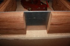
most of the wire connections goes between chassis RCA and switch signal IN
so I guess its most convenient to mount the switch directly on to the backpanel
ought to be doable
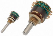
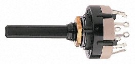
funny to find industruial standard switches looking much like the highend stuff
one of below cost 3USD, and the other 60USD
both with solver contacts and 4-pole options available
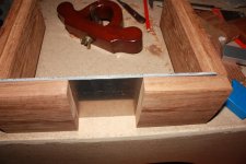
most of the wire connections goes between chassis RCA and switch signal IN
so I guess its most convenient to mount the switch directly on to the backpanel
ought to be doable
funny to find industruial standard switches looking much like the highend stuff
one of below cost 3USD, and the other 60USD
both with solver contacts and 4-pole options available
Attachments
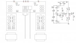
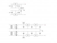
some spec sheets have schematic suggestions
they show it with small poly caps bypassing the 7815
and bipolars on the negative 7915
am I missing something ?
and they suggest to finish with 1N4001 diodes to deal with possible latch-up issues
what does latch-up mean, and are those diodes important ?
they show it with small poly caps bypassing the 7815
and bipolars on the negative 7915
am I missing something ?
and they suggest to finish with 1N4001 diodes to deal with possible latch-up issues
what does latch-up mean, and are those diodes important ?
Attachments
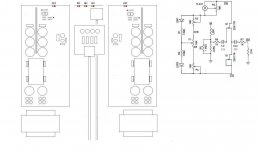
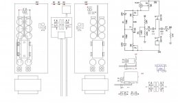
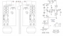
hmm, I guess those are only suggested in/out values relation, be it polar or poly
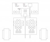
and yet another 'layout'
obviously its going to be completely seperated dual mono
it will definately be easier to wire it this way
and I found some alu to cool the regs
and yet another 'layout'
obviously its going to be completely seperated dual mono
it will definately be easier to wire it this way
and I found some alu to cool the regs
Attachments
Just ad a second pair of output RCAs and wire them to the original pair. Positive to positive, negative to negative.If I want my B1 to have a sub-out how do I do that?
Last edited:
I think from memory that Nelson designed this particular vol control with the buffer for the "3" versions of the LDRs, not the usual "2" ones (rather different impedance range) and intended it to operate over an attenuation range of about 40dB.
If the following load is a "reasonable" impedance (>10kR), shouldn't need the large size 10uF cap on o/p before R7.
If the following load is a "reasonable" impedance (>10kR), shouldn't need the large size 10uF cap on o/p before R7.
I think from memory that Nelson designed this particular vol control with the buffer for the "3" versions of the LDRs, not the usual "2" ones (rather different impedance range) and intended it to operate over an attenuation range of about 40dB.
If the following load is a "reasonable" impedance (>10kR), shouldn't need the large size 10uF cap on o/p before R7.
you mean like NSL-32SR3, instead of NSL-32SR2 ?
wouldn't it be higher impedance ?
maybe its due to the buffer ?
Attachments
The SR3 will go higher in resistance with the same amount of current if I recall the datasheet correctly. They have a much higher off resistance. On the other hand they are spec'd for a 25Megohm off resistance and my DMM goes to 33Megohm. Often the SR2's can not be read on my DMM when they are off. Basically all that says is dont pay attention to the datasheet for these devices. Oh, also SR3 has a higher min resistance of 60R vs 40R. That means your min volume will be louder with SR3.
- Home
- Amplifiers
- Pass Labs
- B1 Buffer Preamp