Hey Keith, Good AM to ya. I am home on a snow day. Do you know the o'l kick the can test. You mentioned that there was no electrical "aroma" during your fateful test flight. Reversing the polarity was perhaps not the best thing for the caps but they did not explode. Things could have been worse. I doubt that the caps are bad. Do you have an ohm meter? If so, attempt to measure the resistance of the caps. There should be an initial "kick" of the meter needle and then it should drift toward a higher resistance. You might also notice an asymmetry of the kick depending on the polarity of the meter leads.
I've connected enough e-caps backwards, always by mistake, The boil inside or overheat, I have yet to explode one. I dont think the current here would do anything but kill them. I would assume they need to be replaced. There is not much else to blow up here, other than the JFETs, and they are probably tuff, and if they didn't smoke your probably good.
Dont give up. We've all messed up and been ready to talk away.
One thing I always do is run equipment in the basement a while before putting into the main system, in case it goes atomic.
Dont give up. We've all messed up and been ready to talk away.
One thing I always do is run equipment in the basement a while before putting into the main system, in case it goes atomic.
To everyone who has been so generous with their help and suggestions.
I may have figured out what was wrong and and am going down to the "lab"(read basement) to fire up the soldering iron and see if I can't get some music to emerge from this lil' box O' horrors.
First of all the HP supply seems pretty much dead when I put the VOM to it. I just happen to have a 15V rated wall wart for the Bent Audio remote volume control control motor that when I put the VOM on it it seems to put out a solid 18V! Of course the polarity of the plug on this "wart" is the opposite of the HP's and the input plug is a different size. I will make the necessary changes and report back soon. It guess it has to be a PITA to make you feel like you have accomplished something? I can't get cocky yet. No sound other than bad sound has emerged from the thing as of yet but I remain hopeful.
Thanks Keith
Last edited:
Hi guys,
progress report.
It is getting better.
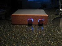
After changing out wall warts and sockets and making damn sure the polarity is correct I have a nice blue glow from the LED and beautiful sound from the left channel. Right channel is still down and out, although there is, if you put your head right against the speaker some very low level noise (hum or buzz) and what almost sounds like crosstalk in the right side.
This seems like it could be a connection somewhere. I am going to study the print I have of the board and do some continuity checking.
Thanks again, and sorry to dominate the bandwidth with my B.S.
Keith Lockwood
progress report.
It is getting better.
After changing out wall warts and sockets and making damn sure the polarity is correct I have a nice blue glow from the LED and beautiful sound from the left channel. Right channel is still down and out, although there is, if you put your head right against the speaker some very low level noise (hum or buzz) and what almost sounds like crosstalk in the right side.
This seems like it could be a connection somewhere. I am going to study the print I have of the board and do some continuity checking.
Thanks again, and sorry to dominate the bandwidth with my B.S.
Keith Lockwood
10:57 PM
It's alive!
I got fishing around with my old analog meter which I much prefer for checking continuity than the digital VOM. Anyway, I suspected a couple of connections to the Goldpoint attenuator. I was a bit intimidated by it and it's tiny and seemingly fragile thin film smd resistors. I really didn't want to overheat a $150 volume control. I was also using a very high purity 23 ga copper hook up wire from Kimber called DTC23that has a special clear and very thin teflon insulation against the copper and a thicker colored teflon jacket over that. With these old eyes I wasn't clearly determining that all of the clear teflon was stripped and so the solder connection at both ends of one wire to the attenuator weren't soldered correctly as I had left insulation on the wire. I looked like a good solder joint but it wasn't.
Sorry I got so freaked! This was my first project like this and I hit the panic button.
The damn thing sounds amazing without any warm up or burn in. I am listening to Tord Gustavsen Trio's "Changing Places". If you like the sound of a small piano combo this is a must listen. It has such a great groove.
I got a little nervous but it turned out great. Now I need another wall wart for use with my remote volume control and I really will be in business. It is a pretty simple installation of the stepper motor and a small circuit board along with a hole in the front panel for the IR sensor. I have never had remote volume before. it should be a treat.
Thanks to everyone who made suggestions, to diyAudio for letting Nelson do this here and thanks so much for your generosity Nelson to share this with us mortals. I feel like I just won an award. the music is playing so it's time for me to shut up.
Thanks again to Colin and everyone at Pass DIY. And special thanks again to Nelson.
Keith Lockwood
That's great news. What a break that you have a functioning channel. You just to need find an asymmetry. A key voltage measurement would be to verify the gate voltages with a high impedance voltmeter to verify to both are at approximately 1/2 VCC. A second measurement would be to compare the ground to source voltage for Q100 and Q200. The voltage on the working channel should be, in your case, .5X18 = 9 VDC. The ground to drain measurements should be 18 VDC (VCC) for both channels. If the voltages for the non-working channel are similar to the working channel then you are down to finding a failed coupling cap or a wiring error. If, on the other hand, if there are identical drain and source voltages on the non-working channel......
You get that thing working and it should be nice with the Goldpoints and the Bent. Are you using dual mono attenuation? Do you have two Bent remotes? Or, if you used a stereo attenuator, how are you going to adjust the balance? Me, I am off to shovel snow.
You get that thing working and it should be nice with the Goldpoints and the Bent. Are you using dual mono attenuation? Do you have two Bent remotes? Or, if you used a stereo attenuator, how are you going to adjust the balance? Me, I am off to shovel snow.
lae2,
I didn't say it clearly enough. BOTH channels are working!
I used a stereo Goldpoint Mini V. I have never found the need for a balance control in this room and two Bent kits with two mono MiniV's would press the budget only further into the nutty zone.
Thanks man for helping me!
I am listening to music again instead of feeling sorry for myself for being a ****up.
Sorry to hear about all that shoveling business. lift with your legs! I am in Michigan and we are luckily missing out on this one where I am.
Keith
lae2,
I don't see why not. Both motors would be connected to the same control board, but run it by John Chapman at Bent Audio. He is a super guy. He goes above and beyond to make you happy. He may even make a special set up for you with two motors and a single control board. He's a great guy and loves DIY'ers.
Don't hurt your back.
Keith
Most likely In = CW, Out = Wiper, Ground = CCW
I agree with you nelson.. Its obvious,

Sam.
.
some might say that no sound is better than bad sound.No sound other than bad sound has emerged from the thing as of yet but I remain hopeful.
I am afraid I am of that ilk. when the quality deteriorates below tolerance level, I leave or turn it off.
Chrismercurio,
Tell me more about how you configure the battery power.
I have been enjoying the sound all day. Frankly I needed a break from,"well I'm not a technician, but I stayed in a Holiday Inn Express last night."
I am an insatiable tweaker but am in no rush to fiddle with it yet.
Thanks,
Keith
Tell me more about how you configure the battery power.
I have been enjoying the sound all day. Frankly I needed a break from,"well I'm not a technician, but I stayed in a Holiday Inn Express last night."
I am an insatiable tweaker but am in no rush to fiddle with it yet.
Thanks,
Keith
Last edited:
[QUOTE
Tell me more about how you configure the battery power.
Keith[/QUOTE]
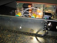
I did it by putting a DTDP switch on the back... one side of the switch has the regular 18 volts and the other side has the battery leads. I also installed a small led that lights when the battery is on; reminds me to turn off the battery. I plan to use 4 x 4.5 volt batts, see picture...
eddie
Tell me more about how you configure the battery power.
Keith[/QUOTE]
I did it by putting a DTDP switch on the back... one side of the switch has the regular 18 volts and the other side has the battery leads. I also installed a small led that lights when the battery is on; reminds me to turn off the battery. I plan to use 4 x 4.5 volt batts, see picture...
eddie
Attachments
Chris...
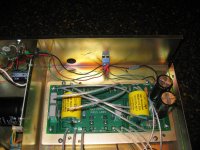
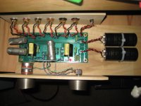
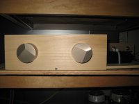
Wood is good! Those are some gnarly looking caps though... kinda your Frankenstein variety. They look like some military experiment gone bad.
They are vitamin q's and are much better sounding than the stock Vishay's. I think the screws on the top made it so that they were solder-less field replacements.
Attachments
Last edited:
- Home
- Amplifiers
- Pass Labs
- B1 Buffer Preamp