Banned
Joined 2002
B-1 101
(I apologize for the length of this post. It took me a month to digest this thread. I managed to remain silent until now.)
I have been studying this circuit for about a month trying to convince myself that I had merely forgot some things from 40 years ago. Truthfully, I have to wonder if I ever knew these things. I roiled over choosing a PSU. I decided on using an AMB Sigma 11 that someone referenced a few posts back. The instructions for my Equitech balanced line conditioner are not favorable toward non-earth grounded plugs. I have a few questions.
C3 has come up a few times in this thread. Its neighbor, C2, was just discussed a few posts back. What if the power supply is a steeply curved low-pass filter (Teddy?). Even though the DC source might be of extremely low noise; could signal transients be softened? That is, if C2 and C3 are omitted and the PSU is a low-pass filter, then might high frequency signal transients round off? On a related note. Why not have a 15001 electrolytic and omit C3.? I imagine that C3 provides a low impedance path to ground for high frequency noise that might otherwise appear at the gate. But, does C3 have any affect on the fidelity of the signal itself? Admittedly with a 1M resister and a gate junction, it seems unlikely that C2-3 could affect signal transients. But then, there is capacitance at the gate. Is this capacitance relevant to fidelity if the power source has limited bandwidth and C2-3 are omitted? Could a transient voltage drop appear across R103/203?
R4 has me. I have been away for awhile so I just learned that there are blue LEDs and that they forward bias higher than 1.8V. At 18v supply, R15 drops 15V and the blue LED 3? Then is 15K chosen to limit the current to 1 ma (R=E/I = 15/.001 = 15K)? I could not fine a light/current specification for blue leds. Do blue LEDs emit light at 1 ma? I intend to load the PS with an on-board led and panel mount D2.
D1 challenges me. I always replaced the condensor along with a new set of points but I never felt comfortable about the physics of collapsing fields and arcing points. Somehow this seems relevant to D1. D1 becomes forward biased when the supply voltage is removed? What is the path for C2-3 to bleed? Without D1 they would bleed through R3. Is the time to no turn-on thump without D1 in the circuit determined by the TC for C2/R3? I may have answered this for myself by looking at the datasheet for the 2SK370. Drain to source current flows at low drain/source voltage levels. Thus, at power shutdown, C2-3 forward bias D1 and then bleed by way of drain/source current through the 4 FETs?
Sorry, I have another question. My intention is to have an earth ground for the chassis and maintain a separate signal ground. The signal ground will have a signal interface (star) to the chassis ground through a "loop breaker." It seems that the burning amp ps uses a thermistor for this connection. I am not entirely confident to say, but it seems that the burning amp description has switched the written description for TH1 and TH3? Could I implement TH1-3 in the same manner? I doubt in-rush current is an issue for the B-1, but I have a long obsession with ground loops. Further, for the B-1, should the thermistor between the signal ground and the chassis ground be bypassed with a capacitor? Perhaps to bleed a possible static discharge to chassis ground?
Oh wait, I have another question. I feel like Columbo. This is my first audio DIY in over 35 years. I am building the B-1 as a reference amp. Depending on how things go, I will build a second B-1 for enjoying music. I am interested in the cable wars and now, inspired by this symmetrical supply subplot, I have become interested in the capacitor wars. I am gradually tweaking my fidelity system into becoming sensitive to changes in hardware - both cables and electronics. I use singled-ended interconnects that have a "symmetrical," also known as "pseudo-balanced," configuration. The signal and return path are symmetrical. The shield is floated at the distal end and, thus, not used for a return path. I intend to route the interconnect cables directly to the B-1 solder pads by passing them through chassis grommets. This gives me the opportunity to ground the shield (floated at the distal end) directly to the chassis. My intention is to connect the return path to the signal ground (there is no choice in the matter) and connect the cable shield directly to the chassis ground. I imagine Marconi already tried this. The shield is otherwise floated. Any problem with this?
I just can't stand the thought of agitated electrons loitering around the shield without being hastily shepherd down a slippery slope into the bowels of the earth.
No matter how much thought I put into this, I fully expect that, once I flip the switch, the speakers will sound like a military chopper.
Thanks for any comments/guidance. Loren
Ps. My first DIY project was a qrp cw radio transmitter that I built back in the 60's (WA6MWX). This B-1 project is a fountain of youth. Thanks Nelson.
I use singled-ended interconnects that have a "symmetrical," also known as "pseudo-balanced," configuration. The signal and return path are symmetrical. The shield is floated at the distal end and, thus, not used for a return path. I intend to route the interconnect cables directly to the B-1 solder pads by passing them through chassis grommets. This gives me the opportunity to ground the shield (floated at the distal end) directly to the chassis. My intention is to connect the return path to the signal ground (there is no choice in the matter) and connect the cable shield directly to the chassis ground. I imagine Marconi already tried this. The shield is otherwise floated. Any problem with this?
I just can't stand the thought of agitated electrons loitering around the shield without being hastily shepherd down a slippery slope into the bowels of the earth.
from.... TheAudioAmateur 5/82 p-57 Letters
CABLE GROUNDING
I would like to offer a suggestion to any readers using balanced cable (two conductor shielded) in single ended applications such as proposed by Bill Ruck in TAA 4/82.
Instead of floating the shield at one end, connect it to ground through a small capacitor ( .01uF ceramic disk). Now the shield will look like it's floating at hum freqencies but will appear grounded at radio frequencies.
This technique is known as "hybrid" grounding and is often used when processing signals that range from DC to RF. The application to audio processing will allow improved RF rejection in wiring schemes such as Mr. Ruck's.
John H. Roberts
Phoenix Systems
Manchester, CT 06040
I've been using this method with my Mogami quad link ICs.
But soon
 will try powering the shields with a DC potential
 as used in $$
$$ cables.C3 has come up a few times in this thread.
R4 has me.
D1 challenges me.
My intention is to have an earth ground for the chassis and maintain a separate signal ground. The signal ground will have a signal interface (star) to the chassis ground through a "loop breaker." It seems that the burning amp ps uses a thermistor for this connection. I am not entirely confident to say, but it seems that the burning amp description has switched the written description for TH1 and TH3? Could I implement TH1-3 in the same manner? Further, for the B-1, should the thermistor between the signal ground and the chassis ground be bypassed with a capacitor?
I use singled-ended interconnects that have a "symmetrical," also known as "pseudo-balanced," configuration. The signal and return path are symmetrical. The shield is floated at the distal end and, thus, not used for a return path. I intend to route the interconnect cables directly to the B-1 solder pads by passing them through chassis grommets. This gives me the opportunity to ground the shield (floated at the distal end) directly to the chassis. My intention is to connect the return path to the signal ground (there is no choice in the matter) and connect the cable shield directly to the chassis ground.
C3 was placed there just to drive audiophiles crazy. If I
didn't put it there, people would want to know why I wasn't
bypassing an electrolytic with a film cap.
R4 sources 1 mA to the blue leds. More current, and people
complain about the bright light.
D1 discharges the reference voltage cap so that when you
unplug the power and then plug it in again you don't get a
thump.
Lastly Colombo, you can try any grounding scenario you
like. If you don't hear noise and distortion, it's probably
good.
Thank you for your comments. Parts are trickling in. I especially thank you for gluing this site and for your contributions toward bringing the world together. I am anxious to discover the path to ground for a bleeding C2-3. I will report back on the grounding successes/failures. Thanks again. Colombo aka Loren
Lastly Columbo, you can try any grounding scenario you like.
Ironically, one often ends up with what was most succesfull in the beginning.
Attachments

B1 PSU Questions
Hello...
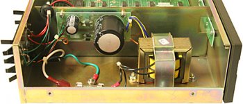
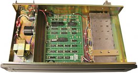
I have ordered the B1 boards from Mr. Pass and I also have ordered the surplus chassis listed in post #2056 (thanks Lee35210)... it comes with a transformer which outputs two voltages +5v and +18v.
The site info for the chassis states "Filter capacitors are 22,000mF at 16 volts and 470mF at 50 volts. The end result is a linear DC +5 volts @ 1.0 amps and +18 volts @ 1.0 amps supply" The transformer output goes to what look like 2 transistors that are heatsinked on the back.
First question: Does "linear" mean regulated... is that what the transistors do?
Second question: Can the outputs of both be combined to total 23 volts?
I know I can run it at the minimum of 18 but I would like to try both voltages if it is possible to combine them.
Last question: If I use this PS do I need filtering caps as Mr. Pass has suggested when using an SMPS?
In spite of being able to assemble one of Peter Daniel's monoblock L3875 kits I can tell you I don't know enough near enough about this subject, but I am learning more and more; especially after reading 2000+ posts on just the B1 thread. I also have ordered Cviller's F5 boards and will be attempting that project as well.
Eddie
Hello...
I have ordered the B1 boards from Mr. Pass and I also have ordered the surplus chassis listed in post #2056 (thanks Lee35210)... it comes with a transformer which outputs two voltages +5v and +18v.
The site info for the chassis states "Filter capacitors are 22,000mF at 16 volts and 470mF at 50 volts. The end result is a linear DC +5 volts @ 1.0 amps and +18 volts @ 1.0 amps supply" The transformer output goes to what look like 2 transistors that are heatsinked on the back.
First question: Does "linear" mean regulated... is that what the transistors do?
Second question: Can the outputs of both be combined to total 23 volts?
I know I can run it at the minimum of 18 but I would like to try both voltages if it is possible to combine them.
Last question: If I use this PS do I need filtering caps as Mr. Pass has suggested when using an SMPS?
In spite of being able to assemble one of Peter Daniel's monoblock L3875 kits I can tell you I don't know enough near enough about this subject, but I am learning more and more; especially after reading 2000+ posts on just the B1 thread. I also have ordered Cviller's F5 boards and will be attempting that project as well.
Eddie
Attachments
Yes, full circle might take 20 years. I recently replaced my "high-end" networked style interconnects and speaker cables with Belden instrumentation wire. The sound became more engaging. I replaced my mega-output device power amp with a much simpler and lower powered 4 output device amp. My system was transformed from the clumsy master of the Grand Finale to the orchestrator of a quiet walk in the forest. I love blackness. Then one day I read ".....suspenders and a belt." Once I recovered from my oceanic feeling, I knew that I would resonate with Pass. I am hoping to transform my system into a delicate creature that performs in the dark. I suspect that the B-1 will move me a bit further in that direction. Great picture! My diet needs some tweaking.Ironically, one often ends up with what was most succesfull in the beginning.
Banned
Joined 2002
Banned
Joined 2002
I have a couple pink/purple LEDs, they are kinda intense.
I bought a bag of the UV purple ones a few years ago, ill use one for this
Fornow im just using this case i have for testing and stuff, hoping to build a really nice regulated dc external psu in a separate case and a pre-amp case with better rca's better 3 source selector switch, and have the B1 tested tuned to my linkings
J'
Hello...
Eddie
I bet those are regulators, you see on the chassis. Take a pic so we can see what they are.
Magura
I bet those are regulators, you see on the chassis. Take a pic so we can see what they are.
Magura
This picture is from the site: The NABU Network - (ENC) 90020340
Eddie
Attachments
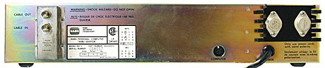
I would need better than average eyesight, to read what's printed on those devices
Closeup please.
Magura
Laff... I don't have the chassis... I just ordered it today! These are the only picts available on the site!
Eddie
? for Magura...bit of a thread jack though
A while back I think you and some others had tried a CLC ps for the Fx amplifiers...can you point me to a schematic?
Best,
Chris
No
I have no memory capacity for what is in which thread.
But drop me a line, and I'll explain.
Magura
Ganging up line filters
I am down to the nitty gritty of parts selection for the B-1. My inclination is to order a filtered power entry module. The ps will be housed in the same chassis as the b-1 board. The low-current (isolated) receptacles on my power conditioner already have line filters. I know that it has been argued that ganging line filters between the wall and a high current amplifier can weaken definition. But, I can't imagine that ganging up line filters on the B-1 would matter. Any thoughts please. L
I am down to the nitty gritty of parts selection for the B-1. My inclination is to order a filtered power entry module. The ps will be housed in the same chassis as the b-1 board. The low-current (isolated) receptacles on my power conditioner already have line filters. I know that it has been argued that ganging line filters between the wall and a high current amplifier can weaken definition. But, I can't imagine that ganging up line filters on the B-1 would matter. Any thoughts please. L
- Home
- Amplifiers
- Pass Labs
- B1 Buffer Preamp