Hi Everyone,
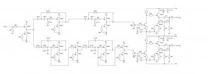
So here's the schematic with (I hope) the corrections Jacques and juma mentioned above. If anyone spots anything else wrong please let me know.
I have some technical questions (again). The buffer circuit I've put in is (I think) the one juma suggested, derived from the one he posted in post #69. I've been scratching my head over some stuff related to this, and I'd be grateful if someone could tell me if I've understood correctly :
:
(juma: I hope I've learned something since the last time you helped me with this stuff!)
1. If Vds, Vgs and Vp are the drain-source, gate-source and pinch-off voltages respectively, then as long as Vds > Vgs -Vp the jfets will be in saturation mode. Looking at the lower BF862 in juma's circuit in post #69, Vp is around 0.8V and max current is Id=40mA, so if we suppose the trimpot is set at 10R (and current entering the gate is zero) then Vgs = 10*Id is no more than 0.4V and Vds =10- Vgs, which is close to 10. So it's in saturation mode, and we can calculate Id by Id=Idss*(1-Vgs/Vp)^2. Taking Idss=13mA (which seems to be typical), I get something like 10mA.
2. This means the upper jfet is passing the same current. (Or nearly so, right?)
3. So each jfet has to dissipate around 100mW. (Approx. 10V * 10mA)
4. If we do the same calculation in the buffer circuit I've posted, where there are no source resistors, we have Vgs = 0 , and we should get Id=Idss, so about 13mA. Up above Jacques suggested +/-9V for B+ and B-, so we would get about 9*0.013 = 0.097W to dissipate, in other words about the same.
So, taking into account that we now have a total of 20 BF862 devices in the circuit, this is a total of 2W to dissipate, which should be OK as long as the jfets aren't all crammed in to too small a PCB. Now, on juma's preamp thread he uses adaptor boards which don't seem to have more than about 1/2 sq. cm of copper on the gates, whereas on the mini-aleph-J amp he helped me on (http://www.diyaudio.com/forums/pass-labs/152379-mini-aleph-using-bf862-possible.html) each jfet was producing about 190mW, and trial and error (!!) showed that a fair bit more was needed (and they still get pretty hot). If I allow about 2 sq cm of copper on the boards for each jfet, does that sound like enough? My best guess is yes, it should be OK, but I'd like to hear opinions, since it's much easier to design this on to the boards than to fit something in later...
Thanks in advance for any help.
Cheers
Nigel
So here's the schematic with (I hope) the corrections Jacques and juma mentioned above. If anyone spots anything else wrong please let me know.
I have some technical questions (again). The buffer circuit I've put in is (I think) the one juma suggested, derived from the one he posted in post #69. I've been scratching my head over some stuff related to this, and I'd be grateful if someone could tell me if I've understood correctly
:(juma: I hope I've learned something since the last time you helped me with this stuff!)
1. If Vds, Vgs and Vp are the drain-source, gate-source and pinch-off voltages respectively, then as long as Vds > Vgs -Vp the jfets will be in saturation mode. Looking at the lower BF862 in juma's circuit in post #69, Vp is around 0.8V and max current is Id=40mA, so if we suppose the trimpot is set at 10R (and current entering the gate is zero) then Vgs = 10*Id is no more than 0.4V and Vds =10- Vgs, which is close to 10. So it's in saturation mode, and we can calculate Id by Id=Idss*(1-Vgs/Vp)^2. Taking Idss=13mA (which seems to be typical), I get something like 10mA.
2. This means the upper jfet is passing the same current. (Or nearly so, right?)
3. So each jfet has to dissipate around 100mW. (Approx. 10V * 10mA)
4. If we do the same calculation in the buffer circuit I've posted, where there are no source resistors, we have Vgs = 0 , and we should get Id=Idss, so about 13mA. Up above Jacques suggested +/-9V for B+ and B-, so we would get about 9*0.013 = 0.097W to dissipate, in other words about the same.
So, taking into account that we now have a total of 20 BF862 devices in the circuit, this is a total of 2W to dissipate, which should be OK as long as the jfets aren't all crammed in to too small a PCB. Now, on juma's preamp thread he uses adaptor boards which don't seem to have more than about 1/2 sq. cm of copper on the gates, whereas on the mini-aleph-J amp he helped me on (http://www.diyaudio.com/forums/pass-labs/152379-mini-aleph-using-bf862-possible.html) each jfet was producing about 190mW, and trial and error (!!) showed that a fair bit more was needed (and they still get pretty hot). If I allow about 2 sq cm of copper on the boards for each jfet, does that sound like enough? My best guess is yes, it should be OK, but I'd like to hear opinions, since it's much easier to design this on to the boards than to fit something in later...
Thanks in advance for any help.
Cheers
Nigel
Attachments
Last edited:
do you really need the 22k pot in the upper (high Pass) filter? It loads the previous stage.
You do not need the the biased electrolytics in the output of the HP stage.
The bass (low pass) looks OK.
Does the second last FET set the correct DC voltage for the single supply last FET?
The four 22nF in the HP should just about fit an 8pin dip header.
The six 22nF in the LP could be fitted to a 14pin dip header or to a pair of 8pin dip headers.
They it's easy to swap 15nF, 18nF, 22nF, 27nF for coarse frequency selection.
Last edited:
Hi Guys,
With regard to the 22k pot in the HP filter, I can see AndrewT's point, but let me ask (as a practical question rather than a theoretical one) if you put the trimpot in the LP section and not in the HP section, and then find the HP section is too loud (say because you have much more efficient tweeters), then how do you compensate? You could always deal with the problem by choosing a stronger power amp for the LP, and turn everything down, I suppose, but that seems inefficient, and how would that compare to (say) putting a fixed 10k resistor in the HP section, so that the LP section can be adjusted up or down relative to it? At least putting a fixed resistor in the HP should be better for distortion than a trimpot (which R-K Rønningstad mentioned), but (of course) it would load the filter in the same way, I suppose. Is there some standard solution I'm not seeing?
I'm sorry, Andrew, I don't understand the question.... The last buffers (after the trimpots) are copies of juma's preamp schematic. I'm treating these things like lego blocks and trying to understand things as I go along. Maybe you could rephrase?
I'm not sure I understand what the biased electrolytics are supposed to do, so I don't know quite how to judge your suggestion to take them out. If I do,
do I replace them with direct connections, or take out the 220k to the negative rail also? (I guess the second...)
I like your ideas about the dip sockets and headers, but I am going to try and standardise on one size... Still some thinking to be done there.
No-one pointed out any errors in my calculations for the lower jfets in the buffer - does that mean understood correctly? - Anyone willing to risk a guess as to whether the cooling I suggested is enough?
Well, as always, thanks for any comments
Nigel
With regard to the 22k pot in the HP filter, I can see AndrewT's point, but let me ask (as a practical question rather than a theoretical one) if you put the trimpot in the LP section and not in the HP section, and then find the HP section is too loud (say because you have much more efficient tweeters), then how do you compensate? You could always deal with the problem by choosing a stronger power amp for the LP, and turn everything down, I suppose, but that seems inefficient, and how would that compare to (say) putting a fixed 10k resistor in the HP section, so that the LP section can be adjusted up or down relative to it? At least putting a fixed resistor in the HP should be better for distortion than a trimpot (which R-K Rønningstad mentioned), but (of course) it would load the filter in the same way, I suppose. Is there some standard solution I'm not seeing?
Does the second last FET set the correct DC voltage for the single supply last FET?
I'm sorry, Andrew, I don't understand the question.... The last buffers (after the trimpots) are copies of juma's preamp schematic. I'm treating these things like lego blocks and trying to understand things as I go along. Maybe you could rephrase?
I'm not sure I understand what the biased electrolytics are supposed to do, so I don't know quite how to judge your suggestion to take them out. If I do,
do I replace them with direct connections, or take out the 220k to the negative rail also? (I guess the second...)
I like your ideas about the dip sockets and headers, but I am going to try and standardise on one size... Still some thinking to be done there.
No-one pointed out any errors in my calculations for the lower jfets in the buffer - does that mean understood correctly? - Anyone willing to risk a guess as to whether the cooling I suggested is enough?
Well, as always, thanks for any comments
Nigel
....
...Does the second last FET set the correct DC voltage for the single supply last FET?...
I'm sorry, Andrew, I don't understand the question....
No one can claim he does, but let me try to guess.
We are speaking about the preamp (three most-right JFETs in your sch.). The first one is the voltage amplifier (we'll call it Q1) and Q1's Drain is on the +12 to +14V potential (roughly half of the +V=24V). Q1's drain is connected to the Gate of the Source Follower JFET (we'll call it Q2). That's the right voltage to allow maximum voltage swing of the preamp (see B1 - it also has it's Source Follower's Gate sitting on the half of the +Vc).
If this doesn't answer the question, please mark the parts in you sch. Q1 - Qn, ... R1 - Rn ... C1-Cn etc.. and let Andrew rephrase the question more precisely.
Biased ELKOs are two ELKOs on the preamps output which are polarised to -4.6V. I do it because I find that if used that way, ELKO's leave minimal sonic imprint when used as coupling capacitors. Of course, single 10uF teflon film cap is a better solution (if you can afford it) and the capacity of that cap depends on the next stage's Zin - for HP output it can be very small - you are making a filter after all, right?
Last edited by a moderator:
Noone can claim he does, but let me try to guess.
We are speaking about the preamp (three most-right JFETs in your sch.). The first one is the voltage amplifier (we'll call it Q1) and Q1's Drain is on the +12 to +14V potential (roughly half of the +V=24V). Q1's drain is connected to the Gate of the Source Follower JFET (we'll call it Q2). That's the right voltage to allow maximum voltage swing of the preamp (see B1 - it also has it's Source Follower's Gate sitting on the half of the +Vc).
If this doesn't answer the question, please mark the parts in you sch. Q1 - Qn, ... R1 - Rn ... C1-Cn etc.. and let Andrew rephrase the question more precisely.
Your explanation makes sense to me, but in any event, I will post schematic with labelling on everything, although it's a little late tonight.
Biased ELKOs are two ELKOs on the preamps output which are polarised to -4.6V. I do it because I find that if used that way, ELKO's leave minimal sonic imprint when used as coupling capacitors. Of course, single 10uF teflon film cap is a better solution (if you can afford it) and the capacity of that cap depends on the next stage's Zin - for HP output it can be very small - you are making a filter after all, right?
I understand the value needn't be large on the HP part - I presume a 10uF (or whatever size) would just substitute the 1.5uF shown, right?
So did my post #82 make sense? (I scratched my head over it so long I'd really like it if someone would tell me if it's wrong...
)Cheers
Nigel
Of course, single 10uF teflon film cap is a better solution (if you can afford it) ...
A Hovland might make a somewhat more economical choice here, too. Something of a middle ground solution
. By al means size them sensible based upon the That buffer you added to the LP section was what I meant. I'll take a closer look at the last schematic you posted and comment. I just didn't get a chance today.
WRT the earlier comments about which pots, etc., you may or may not need -- if you are laying out a PCB may I suggest that you leave them in. That will provide the maximum flexibility for any future systems you may wish to use the board in. You can easily leave any unneeded components unpopulated and use jumpers to make the connections. Likewise, once you have arrived at the final attenuation figures you could replace any remaining level setting pots by a fixed resistor divider.
....
I understand the value needn't be large on the HP part - I presume a 10uF (or whatever size) would just substitute the 1.5uF shown, right?..
The value of coupling cap on the output of the HP part depends solely on the next stage's Zin. If your next stage is F5 (with 101k Zin) 1uF will do.
That 1u5 cap is a bypass over the polarized ELKOs (I use Siemens stacked foil).
Coupling caps are subject of many debates. Everyone has his favourite solution, this is mine. Feel free to experiment.
Hi,
Juma's explanation of how DC is handled is OK.
The HP filter with the existing 22uF+22uF//1u5F gives an equivalent 12.5uF and that has a f-3dB of 1.3Hz into a 10k Rin amplifier.
That is good for a true sub-bass amp. Probably too low for a bass/mid amp and plain unnecessary for a mid/treble or treble amp.
The 1u5F alone has F-3dB of 11Hz and allows all frequencies above 100Hz to pass. This would do for a mid driver.
470nF (F-3dB=33Hz) would do for a treble driver that rolls off >=350Hz.
The two back to back electrolytics with the biasing resistor from -ve, are only needed for low bass or sub-bass drivers/amplifiers.
The treble driver and the bass/mid driver and the low bass driver all have different requirements for Vpk and Ipk. Each amplifier should be selected or designed to meet that Vpk & Ipk requirement to deliver the required SPL at the listening position. This demands different amplifiers with different voltages and different currents and can easily have different gains selected to suit the different drivers. An attenuator adjustment on the treble filter is simply a waste.
BTW,
Rin=100k will lower the coupling cap frequency a full decade compared to the example figures quoted above.
Yes, a 22nF coupling cap and 100k for Rin allows 750Hz to pass unhindered.
Last edited:
Hi Everyone,
My version of this project is proceeding, but I have put the final design of the crossover on hold while I figure out what to do about speakers, since this may affect things, of course. (There is a thread on the MultiWay forum if anyone is interested:
http://www.diyaudio.com/forums/multi-way/157147-brazilian-woofer-specs.html)
Meanwhile, here is part of the big picture. The project is a preamp which incorporates this crossover, with the last output buffers (the ones with gain) on separate boards. The preamp will have jumpers inside the chassis to switch between full-range use, using just one pair of the output buffers (the oines with gain), or for bi-amping, with the filters in use. (This won't be switchable from the outside). The filter boards will have the IC sockets discussed above so that crossover point can be changed also. So I am building the chassis and the output buffers first, leaving sufficient space inside for the filter boards tobe done, when design is finalised.
Here's a question, however. I need to decide on the transformers and PSU requirements now, since chassis layout depends on this. The output buffers need +24.6 V and -4.6 V, and the filters need +/- 9V. I can see no way to meet these requirements with one transformer, so unless anyone has a better suggestion it'll have to be two. Now, as far as power requirements go, there are a total of 14 buffer circuits in the filters, so with about 10mA in each jfet pair, am I right in thinking the filters will draw a total of 140mA? How large a trafo do you think will be necessary for comfort? Here in Brazil trafos are sold by current rating, not power; a 600mA 12-0-12 trafo should be sufficient by this estimate, but is only 40VA, where the symmetrical B1 thread suggests 50VA just for one buffer... A 1A trafo is no problem, but a 2A trafo starts to seem like overkill. (And would generate biggermagnetic field, and so forth,a also...) Does anyone have an opinion on this?
Secondly, (although OT, strictly speaking) to get voltages for the ouptut buffers, can I use a 12-0-12 trafo with one "12" as ground to give 24 - 12 - 0, and then rectify the 0-12 and 0-24 separately? The alternative would be to use separate trafos, but this would now give a total of three in the chassis,which seems like it should be unnecessary.
Thanks for any help
Cheers,
Nigel
Hi,
if your quiescent current is 140mA then your transformer MUST be greater than or equal to 560mAac.
look at your highest voltage requirement. That will determine the Vac of your transformer. You will need 24Vac to get a regulated +24.6Vdc.
The other 24Vac winding can be split into two or three windings, each producing a different regulated voltage.
10Vac & 10Vac will give you +-9Vdc regulated.
That leaves 4Vac plus a few tens of turns to give 6Vac to make your final -4.6Vdc regulated.
24+24 @ 560mA >=27VA, look for 30VA to 60VA toroid or even as big as 100VA and some 0.5mm or 0.6mm diameter enameled copper wire to add the extra turns.
Why so low, +-9Vdc, for the filters?
Last edited:
NP says "The preamp typically draws fewer that 0.02 Amps, so
current is not much of an issue." That is the B1, with one buffer per channel. So depending on amplifier stages in the filter you should multiply with that number, I believe. 0.02A is 20 milliAmpere so even a LR4 with everything does not consume much.
Your 140 mA from 24 V is slightly more than 3 W, so a 40VA trafo should suffice...
Good luck!
Hi AndrewT
That's clear enough (although I'd still like someone to confirm I estimated total current draw the right way...). It means that for the filters I'll be fine with any of the above trafos.
Sorry, I'm not sure I understand this part. Are you suggesting I unwind/rewind a 24-0-24 trafo to make all the voltages I need? (I'm not against giving this a go, although I've never done aything like it before... ) In this case, then, I'd unwind to the centre-tap, cut the wire to give a 0-24 winding, then rewind the correct (??!!??) number of turns for each voltage you mention. Sounds quite an adventure!!
Did I understand correctly?
How do you fix the ends of the windings? Any link to a site showing how it's done?
No chance of rewinding a toroid, I'm afraid. Here in Brasil I'd have to have the trafo specially wound, which isn't out of the question, but does take the fun out of things... Any reason I can't do this with an EI?
Thanks.
Nigel
Hi,
if your quiescent current is 140mA then your transformer MUST be greater than or equal to 560mAac.
That's clear enough (although I'd still like someone to confirm I estimated total current draw the right way...). It means that for the filters I'll be fine with any of the above trafos.
look at your highest voltage requirement. That will determine the Vac of your transformer. You will need 24Vac to get a regulated +24.6Vdc.
The other 24Vac winding can be split into two or three windings, each producing a different regulated voltage.
10Vac & 10Vac will give you +-9Vdc regulated.
That leaves 4Vac plus a few tens of turns to give 6Vac to make your final -4.6Vdc regulated.
Sorry, I'm not sure I understand this part. Are you suggesting I unwind/rewind a 24-0-24 trafo to make all the voltages I need? (I'm not against giving this a go, although I've never done aything like it before...
) In this case, then, I'd unwind to the centre-tap, cut the wire to give a 0-24 winding, then rewind the correct (??!!??) number of turns for each voltage you mention. Sounds quite an adventure!! Did I understand correctly?
How do you fix the ends of the windings? Any link to a site showing how it's done?
24+24 @ 560mA >=27VA, look for 30VA to 60VA toroid or even as big as 100VA and some 0.5mm or 0.6mm diameter enameled copper wire to add the extra turns.
No chance of rewinding a toroid, I'm afraid. Here in Brasil I'd have to have the trafo specially wound, which isn't out of the question, but does take the fun out of things... Any reason I can't do this with an EI?
Thanks.
Nigel
you would have to remove the bobbin to unwind the turns. That requires a complete dismantling of the transformer core. I wouldn't do that.Are you suggesting I unwind/rewind a 24-0-24 trafo to make all the voltages I need? (I'm not against giving this a go, although I've never done aything like it before...
................. Any reason I can't do this with an EI?
Yes, a toroid has most, maybe all, of the turns exposed around the circumference of the transformer.
This makes it very easy to measure voltages at the turns by just scraping off a tiny bit of enamel.
When you find the correct locations, just snip the turn and solder on new flexible ends. Remember to varnish the scraped areas before putting the outer insulation wrap back on.
Alternatively.
create +-24.6Vdc and regulate down to the other voltages.
NP says "The preamp typically draws fewer that 0.02 Amps, so
current is not much of an issue." That is the B1, with one buffer per channel. So depending on amplifier stages in the filter you should multiply with that number, I believe. 0.02A is 20 milliAmpere so even a LR4 with everything does not consume much.
Your 140 mA from 24 V is slightly more than 3 W, so a 40VA trafo should suffice...
Good luck!
I answered AndrewT's post before I saw yours. Thanks for the confirmation.
you would have to remove the bobbin to unwind the turns. That requires a complete dismantling of the transformer core. I wouldn't do that.
D**n.... I'd gotten quite excited about having a go at this...
Yes, a toroid has most, maybe all, of the turns exposed around the circumference of the transformer.
This makes it very easy to measure voltages at the turns by just scraping off a tiny bit of enamel.
When you find the correct locations, just snip the turn and solder on new flexible ends. Remember to varnish the scraped areas before putting the outer insulation wrap back on.
Alternatively.
create +-24.6Vdc and regulate down to the other voltages.
Any toroid here would have to be specially wound, so there isn't much point to rewinding one. (Although it's interesting to read about...) I thought about regulating down, but I can't help feeling that it would be better to go with two trafos in this case - one symmetrical PSU with a 12 - 0 -12 centretapped trafo (a 2A version, say, which would be 48VA) feeding the filters, and a separate one with a 24- 0 -24 centretapped trafo (600mA or even 300mA should be enough) feeding the two output buffers after regulators and so forth. Compared to one trafo the only disadvantages are space, and an increase in magnetic field issues (shouldn't be too significant) and the advantage is a simpler pre-regulation. (+24.6 is already designed into the circuti from 24VAC - -4.6V would require pre-regulation - perhaps 7924 followed by 7915, or something, to minimise heat issues.) Did I miss anything? (Or misunderstand anything?)
Cheers
Nigel
A pair of 7815/7915 after +-24.6Vdc would be a very simple and cheap and space saving way of powering the filters.+24.6 is already designed into the circuti from 24VAC - -4.6V would require pre-regulation - perhaps 7924 followed by 7915, or something, to minimise heat issues.)
Then 7905 for the negative supply.
Check your currents and voltage drops and dissipations to see what needs heatsinks and what might get away without.
Remember to check for highest mains voltage on the first regulator and again lowest mains voltage to ensure no drop out.
Actually, I think I can answer my own question... On the symmetrical B1 thread I see that Salas' shunt regulator uses +/- 17 V on input - pregeulating a +/- 24V to get that would be fine. (I'll have to adjust a little since I want +/- 9V, but that shouldn't be a problem. In this case one trafo is better.
I presume Salas' shunt regulator will handle 14 of these buffers instead of two? (A little off-topic, I guess...) No current draw problems? (Maybe heatsink the IFP240's a little better...)
Cheers
Nigel
I presume Salas' shunt regulator will handle 14 of these buffers instead of two? (A little off-topic, I guess...) No current draw problems? (Maybe heatsink the IFP240's a little better...)
Cheers
Nigel
Hi Guys,
I would like to report some success. I had been toying with this idea of using a B1 for active crossover using Sallen-key filters for over an year, but some how never got around to building it. Finally I built one channel P to P on a proto board. Th improvement in sound quality over my passively crossed over speakers are huge. However, building it P-P is just too much work and a big challenge. Not recommended for noobs.
The sound is so much more fuller and rich. The notes well defined, you can sense the separation between instruments so well. My son can't wait for me to get the other channel finished.
Dave (Planet-10),
You really should give this a try, it might change your mind about Sallen-key filters.
Regards,
Dinesh
- Status
- This old topic is closed. If you want to reopen this topic, contact a moderator using the "Report Post" button.
- Home
- Amplifiers
- Pass Labs
- B1 Active Crossover