Hi everyone...
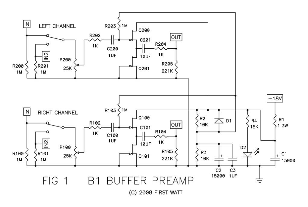
I've just finished my new B1. Schematic taken from Passlabs. But there is only dead silence at the outputs.
Here is the schematic:
Here is my layout:
I can't find any mistake... So please anyone help me with this problem.
I've just finished my new B1. Schematic taken from Passlabs. But there is only dead silence at the outputs.
Here is the schematic:
An externally hosted image should be here but it was not working when we last tested it.
Here is my layout:
An externally hosted image should be here but it was not working when we last tested it.
I can't find any mistake... So please anyone help me with this problem.
Your images --
If you can take any voltage measurements anywhere, that will help.
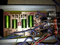
Also, could you take some photos of it and post them here?
For reference, the Original B1 schematic -
An externally hosted image should be here but it was not working when we last tested it.
An externally hosted image should be here but it was not working when we last tested it.
If you can take any voltage measurements anywhere, that will help.
Also, could you take some photos of it and post them here?
For reference, the Original B1 schematic -
Last edited:
Oh... I took some voltage measurements. VCC behind the smoothingcaps is 18,68V. I used 2SK170 as mentionend in the Passlabs article. No matching. I only want to see if this gem is working. But it won't make any noise.
Where are positions to measure which would be interesting?
I can take some pictures of the inside tomorrow when i'm back from work.
Where are positions to measure which would be interesting?
I can take some pictures of the inside tomorrow when i'm back from work.
Yes, the photos of the preamp are visible. ")
Looking at your layout it seems that you have the signal going to the source of the 'top' transistor. I could be wrong, it's hard to see.
Check your transistor layout.
Here is the datasheet for the 2sk170
www.datasheetcatalog.org/datasheet/toshiba/1027.pdf
Looking at your layout it seems that you have the signal going to the source of the 'top' transistor. I could be wrong, it's hard to see.
Check your transistor layout.
Here is the datasheet for the 2sk170
www.datasheetcatalog.org/datasheet/toshiba/1027.pdf
Last edited:
Hi xandrell,
Is far as I can see, you used the pin layout of the IRF 610 or IRF 9610 were the gate is on the left side looking on the front of semiconductor, where the words are, but Sk170 has the gate in the middle and the drain and source outside.
So check your j-FETs and solder them new twisting the legs!
http://www.datasheetcatalog.org/datasheet/toshiba/1027.pdf
6L6 is right!
Last edited:
If the board was designed for IRF610, then yes, you need to get a bit of teflon tubing and insulate a lead or two and cross the legs.
For reference, IRF610 datasheet -- http://www.hebertech.com/datasheet/vishay/irf610.html
For reference, IRF610 datasheet -- http://www.hebertech.com/datasheet/vishay/irf610.html
Pin 3 to slot 3, isn't then the drain of J-Fet connected to the source place of IRF holes?
In German im zweiten Pinbelegungsbild sieht man den Transistor von unten und im ersten von der Schriftseite.
It is so easy to get confused by the pin pictures, reflect 5 times please!
At least for me!
Nevertheless you did a fine work!
In German im zweiten Pinbelegungsbild sieht man den Transistor von unten und im ersten von der Schriftseite.
It is so easy to get confused by the pin pictures, reflect 5 times please!
At least for me!
Nevertheless you did a fine work!
Last edited:
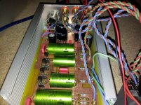
Updare... After twisting pin1 and 2 and rotating the hole mosfet... Well... It works ;-) No audible hum at the output... Only that what you give him. But i have one question left: is there a possivility to raise the gain just a bit? Let's say about 3 or 6db?
So really thanks for the gelp and hints on this project.
So really thanks for the gelp and hints on this project.
I'm using my DVD-Player and my Receiver for input. Amplifier(s) are mainl a TDA2050 chipamp (own design) and a Mini-A. Maybe i'm going to tune my receiver to get more signal at the output ;-)
Here's a pic of it running:
Here's a pic of it running:
An externally hosted image should be here but it was not working when we last tested it.
Last edited:
- Status
- This old topic is closed. If you want to reopen this topic, contact a moderator using the "Report Post" button.
- Home
- Amplifiers
- Pass Labs
- B! finished - HELP needed...