It's 125w x 5 plus 65 x2. I wouldn't say it's bad. It's actually good but I subjectively judge the B&K higher. Since I recently got it, I need to do more listening tests to be specific.
The thing is rather heavy -- 70 lbs.
Of course, I'm also comparing the B&K receiver to the Denon/Emotiva combination. Scientifically, if it would be faulty to state that any difference is due to the Emotiva. I can hook-up a B&K 5000 amp I have -- which has essentially the same amp section as the AVR-202, to perform this test.
Hey MTA and all,
It's been very hectic for me the last few days and will be for the next few weeks. I'm getting ready to move into a new apartment for the semester and wrapping up my lease of the old one. This will put a damper on my free time, but I'll try to make some progress... You think of summer as the part of the year where you can finally have the time to do what you want, but it seems to not be the case. Anyway, I'll try to keep things moving when I can, and will post any new developments.
Iain,
As far as potentiometers go, what kind of specs should I get for use as a level control? I've been looking at options and there are so many to choose from. The taper (ex:linear, audio, ect)? The resistance rating? The wattage rating?
Likewise for the test load resistor; digikey has hundreds of configurations and styles and I'm a little lost as to what would be best for my needs.
What is the benefit of slow blow fuses in this situation vs fast?
What do you mean by "Tie enable low" ?
Can I connect only one channel to the PS and test it, or do I need to have all of them plugged in for balance?
Thanks")
It's been very hectic for me the last few days and will be for the next few weeks. I'm getting ready to move into a new apartment for the semester and wrapping up my lease of the old one. This will put a damper on my free time, but I'll try to make some progress... You think of summer as the part of the year where you can finally have the time to do what you want, but it seems to not be the case. Anyway, I'll try to keep things moving when I can, and will post any new developments.
Iain,
As far as potentiometers go, what kind of specs should I get for use as a level control? I've been looking at options and there are so many to choose from. The taper (ex:linear, audio, ect)? The resistance rating? The wattage rating?
Likewise for the test load resistor; digikey has hundreds of configurations and styles and I'm a little lost as to what would be best for my needs.
What is the benefit of slow blow fuses in this situation vs fast?
What do you mean by "Tie enable low" ?
Can I connect only one channel to the PS and test it, or do I need to have all of them plugged in for balance?
Thanks
Slow
Iain,
How did you figure out to try 0.75A slow blow fuses? Are you looking at the avr307 schematic? The ones in the avr 307 schematic are 6A slow blow, while the ones in my avr 202 are 4A, 250V (not sure if slow blow or not, but probably are). Should I use a different value based on the 4A, or is 0.75 A slow still a good value to try?
Also, what did you mean by "Tie enable low" ?
I think I'm supposed to use logarithmic pots, since decibels are also on a log scale. Is that correct?
I may seem hesitant, but I don't want to chance blowing up my last remaining hopes for this amp
Thanks again!
So you'll need an "audio" or A taper pot which has log scale. They're usually marked after the value e.g. "10KA"
If you're inserting between (e.g.) a CD player and the amp then you could probably get reasonable performance with a pot between 10K and 100K. This assumes the CD player has constant output impedance vs freq and amp has constant input impedance. But it's a good starting point.
Power is negligible. 1/4W is plenty.
Tie enable low = connect the CTRL pin to ground (I called it by a different name - sorry
My thinking on the fuse was to pick a very low current that even at a 2X peak couldn't damage the output devices. You need a slow blow to survive the initial turn on current. These fuses would only be for a turn on test. If the outputs center at 0V and it passes a small signal you can replace the specified fuses.
Did you draw the hook up? Take a picture and post it
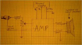
I'm not sure what exactly you wanted to see in the diagram. I sketched a basic idea for a single amp module and you can see it in the picture below. I treated the amp and power supply as black boxes with their corresponding ins/outs.
The output side is unchanged.
The only thing changed on the power supply side is that CTRL is is tied to GND.
I would connect a pot as shown after the input source signal.
All grounds in the diagram are connected to the main amp ground point which is connected through the chassis to the mains ground.
^^^ How does it look?
When I am testing this setup, I was going to use only one module. For the other modules, do I just leave the input pins unattached to anything? Do I connect only the ground pin to ground and leave the input signal pin open?
Attachments
The drawing should represent all the physical connections you're making to the amplifier so you can check that it's all there and that all currents flow in the correct loops.
From what you say, it sounds like you're building the amp modules into the existing chassis using the regular connections except for signal input and CTRL? So on your diagram, the CTRL should originate from the amp and terminate at the star point (ground symbol). The connection to the PSU is confusing - do you connect the orange wire to ground or have you wired the PSU end of CTRL to ground? . These are the details that are important and there's so many, it's easy to miss one.
From the schematic, the ground at the signal input connector isn't connected to the ground on the speaker output connector. The grounds need to be tied together at the star point. If you're not connecting through the pre-amp section you'll be missing this link. You'll need to add an extra connection from the input jack ground to the star point.
For the other channels, don't connect the PSU lines or the input lines. Just leave it all open.
Hmmm.
For the grounds: there is a bolt rising up from the floor of the chassis to which many green wires are connected. I can only assume that this is the main star connection for the grounds. It was my intention to connect all of the aforementioned grounds to this point (including the one for the source input.)
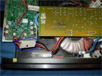
I was thinking to solder the ground wire to the CTRL terminals on the PSU (the orange outline on the picture.) I was hoping I could keep the other connections intact, but I take your meaning differently now.
You are saying to DISCONNECT the CTRL wires from the PSU entirely and lead them to ground INSTEAD. Is that correct?
The three wires running from the PSU to the amp modules (V+ red, CTRL orange, V- black) are connected by way of a single white clip between the components (blue outline in picture).
*The other option that you mentioned earlier was to short circuit the resistor in the CTRL circuit of the amps (R30 in the avr307 schematic?). Would that be better than running the CTRL to ground?
For the grounds: there is a bolt rising up from the floor of the chassis to which many green wires are connected. I can only assume that this is the main star connection for the grounds. It was my intention to connect all of the aforementioned grounds to this point (including the one for the source input.)
I was thinking to solder the ground wire to the CTRL terminals on the PSU (the orange outline on the picture.) I was hoping I could keep the other connections intact, but I take your meaning differently now.
You are saying to DISCONNECT the CTRL wires from the PSU entirely and lead them to ground INSTEAD. Is that correct?
The three wires running from the PSU to the amp modules (V+ red, CTRL orange, V- black) are connected by way of a single white clip between the components (blue outline in picture).
*The other option that you mentioned earlier was to short circuit the resistor in the CTRL circuit of the amps (R30 in the avr307 schematic?). Would that be better than running the CTRL to ground?
Attachments
Iain McNeill said:The drawing should represent all the physical connections you're making to the amplifier so you can check that it's all there and that all currents flow in the correct loops.
I count 7 contact points connected to each amp module. These are the connections that I portrayed in my drawing.
They are:
V+
V-
CTRL
0V (to black speaker terminal and ground)
output (to red speaker terminal)
pin 3 (input gnd)
pin 5 (signal input).
Should I have also included the transformer and mains connections? What else are you looking for?
1000x sorry for my ignorance
I've been doing a lot of research and practice lately, though I've been running short of time in the past few weeks.You're doing good. But the urge when frustrated is to do something, anything. Usually bad. Some calm thought ahead of action is best.
The CTRL line is very forgiving of where it is grounded. But I'm not clear from your drawing & description exactly what path CTRL on the amp board takes to the star point. Is there a hard connection or is it through the PSU board and the red/black/orange connector?]
The audio input ground is important because it can generate transistor and speaker destroying DC offsets at the output. You say you connected the audio input to star point ground but did you also connect the amplifier input ground? It's a menage a trois as they say
Everthing's connected in the original chassis, right?
edit: yes that bolt is star ground
Iain McNeill said:You're doing good. But the urge when frustrated is to do something, anything. Usually bad. Some calm thought ahead of action is best.
*Takes deep breath*
Iain McNeill said:The CTRL line is very forgiving of where it is grounded. But I'm not clear from your drawing & description exactly what path CTRL on the amp board takes to the star point. Is there a hard connection or is it through the PSU board and the red/black/orange connector?
In the photo of the boards, I hadn't connected anything to ground yet. The V+, V-, CTRL wires are hardwired to the PSU in rows of three near the orange circle I drew. They are also hardwired to the amp module, but all three can be disconnected by means of the white clip which is circled in blue.
When I originally attempted to ground the CTRL lead, I simply attached a wire to one of the terminals (circled by orange in the photo) with an alligator clip, and ran it to the star ground.
Iain McNeill said:The audio input ground is important because it can generate transistor and speaker destroying DC offsets at the output. You say you connected the audio input to star point ground but did you also connect the amplifier input ground? It's a menage a trois as they say
The way I hooked it up originally:
From the RCA jack
>> central pin of RCA plug goes straight to the input on the amp (pin 5).
>> sleeve of RCA plug went to pin 3 (input gnd). It shared with this pin a connection to the star ground on the chassis.
Iain McNeill said:Everthing's connected in the original chassis, right?
Correctamundo
I'm not going to attempt a transplant until I can get everything working in its original habitat.Whoooo..... work in the morning, so that's it for me tonight. Thanks for your help in clarifying things. I know it can be tough trying to sort out the pleas of a newbie!
Parts!
The parts I ordered just arrived today. I'm going to try implementing things one at a time and take readings to make sure everything is okay before proceeding forward.
Here's what I got:
Log Potentometers
RCA jacks
0.75A slow blow fuses
7.5 ohm wirewound 5W resistor
8.2 ohm ceramic 5W resistor
You said that I could operate one module at a time right? So I'm going to leave all other 4 modules completely disconnected from anything while testing my configuration. I'll put in the test fuses, and wire CTRL to ground. I'll hook up the RCA jack and pot on the input side and connect one of the resistors across the speaker terminals for that channel.
What should I test while using the low amp fuses? When will I know it's okay to put the normal fuses in? With what else should I concern myself? Thanks, as always
Just check that the output is close to 0VDC (up to 100mV offset is OK) check the rails are where they should be and then input a very small signal - start with the pot at minimum (wiper at ground) and turn it up slowly. You should see some AC volts across your load resistor - don't exceed more than 5VAC or so. You could even put both resistors in series for a 16ohm load if you're very paranoid (like me).
If all is well you can replace the fuses and go for some heatsink warming power
Make sure all your connections are in place first paying attention to ground!!
If all is well you can replace the fuses and go for some heatsink warming power
Make sure all your connections are in place first paying attention to ground!!
))))Well, I hooked everything up to one of the modules, double checked all my connections and ran the preliminary tests with the 0.75A fuses. I hooked up my PSP and set some music playing. I'll be honest, I was a bit scared to turn the potentiometer up at all. I was ECSTATIC when I saw the VAC across the resistor increase as I turned it up.
I'm going to plug in the regular fuses now and do some more testing with the resistor loads. What else should I do at this point? How will I know it's okay to hook up a speaker?
I AM SO EXCITED!!!
With my PSP at max volume and the pot turned all the way up, I'm getting an AC voltage that peaks a little lower than 5V across the resistor. Is this the kind of reading I should expect?
EDIT:
Ok, I couldn't wait, so I did a few searches for some rough estimates on speaker voltages. Hoping that less than 5V AC was safe, I hooked up my last crappy Sony speaker and turned up the pot. SUCCESS!!!
I don't have time to finish the other channels tonight, but I'm going to do work on it first thing tomorrow.
Any suggestions for things I should do at this point to ensure reliability and safety of the amp? Obviously I'd like to hook this up to my good speakers, but I'd like to be assured of it's safety before I do.
Another question. Is that simple pot volume control hindering the quality of the signal at all? I read that there are much better volume controls out there.
EDIT 2:
HMMM... When the receiver was fully functional, it seems like it was much louder. When my pot is all the way up, it's fairly loud, but not nearly as loud as it was before. Could the line level of the PSP be low, or is this because I'm missing a preamp section? Hmmm indeed.
Congrats! You are now an official modder!
The low level could be because the pot is loading down the player. What value are you using? It may also roll off a little low end due to the input cap. A buffered pot like Nelson Pass' would be an upgrade for you (now you're addicted like the rest of us )
Or maybe the removed preamp section had some gain?
You should be able to get up to 40Vrms with 65V rails and a 1-2Vrms input although this would flash-fry your 5W resistors. What input voltages are you seeing on the PSP output and pot wiper?
The low level could be because the pot is loading down the player. What value are you using? It may also roll off a little low end due to the input cap. A buffered pot like Nelson Pass' would be an upgrade for you (now you're addicted like the rest of us
)Or maybe the removed preamp section had some gain?
You should be able to get up to 40Vrms with 65V rails and a 1-2Vrms input although this would flash-fry your 5W resistors. What input voltages are you seeing on the PSP output and pot wiper?
Thank you! And I do mean that specifically; I really appreciate your patience in helping me. Couldn't have done it without youCongrats! You are now an official modder!
Even though I have more to do on this, I feel like the hard part is over (figuring out what to do to get it working alone). Now I just have to apply the same connections to the other four channels.~~~~~~~~~~~~~~~~
The lower volume must have been because of the input. I was using an MP3 player the first time, and when I hooked it up to my PlayStation 3 the volume went up significantly in comparison. Hmm. I'm still without a dedicated preamplifier of any sort (my friend's Sony receiver has no Pre-Outs), so I'll have to wait for the true test.
What does the multimeter measure? VAC RMS? You say I should be able to get up to 40V RMS? I took readings across the terminals at max volume to get peaks of about 11 VAC.
The low level could be because the pot is loading down the player. What value are you using? It may also roll off a little low end due to the input cap. A buffered pot like Nelson Pass' would be an upgrade for you (now you're addicted like the rest of us )
I got some 50k Ohm pots. I just kinda took the difference of your suggestion between 10k and 100k. Is this buffered pot just a capacitor in series with the source input? Does the kind of volume control I've implemented introduce much distortion (by volume control standards)?
I got all 5 channels functioning now, and I've even mounted the pots and RCA's into the back panel. As far as I'm concerned, it's exactly what I need. I was listening to music for several hours last night; it works amazingly with my Infinity Beta 50 speakers. Still have no preamp though... running stereo from my PS3.
Now that I've got my feet wet... I figure it's time to look for improvements I can make. Maybe I should put that in a new thread, since the title of this one still revolves around the buzzing relays...
Anyway, MTA; what would you like to know, and how can I help you with your 307 project? Do you want to start on your 202 to get an idea of my setup? Do you want to move this over to your thread?
Still have no preamp though... running stereo from my PS3.Now that I've got my feet wet... I figure it's time to look for improvements I can make. Maybe I should put that in a new thread, since the title of this one still revolves around the buzzing relays...
Anyway, MTA; what would you like to know, and how can I help you with your 307 project? Do you want to start on your 202 to get an idea of my setup? Do you want to move this over to your thread?
Ok, if I'm actually going to use this sucker, I'm obviously going to use it with some sort of preamp. I tested it with a friend's today and set the amp levels all to about 90%. There was a distinct hum when the preamp was turned on. When the amp is on at full volume (pots all the way up) and is disconnected from any preamp, there is no hum in the speakers at all. I'm assuming this hum/buzz is some sort of ground issue, though I'm not sure where to start. It's quite audible and very annoying.
The B&K is using a 3 prong computer-cable-style mains plug.
The Preamp is a Harman Kardon avr 247, and it only has a two prong mains plug. Could this be part of the problem?
I would think that any powerful AV equipment should have a mains ground plug instead of the two prong type... For safety reasons. Why would HK use a two prong plug for an AV receiver???
It's cheaper
OK, now we get into details. Do some trolling around the forum as I have seen some very excellent dissertations on ground philosophy. The upshot is that the source is an antenna for mains leakage current which flows in the shield of the input cable. Therefore, the input jack ground must be tied directly to the star point so that the leakage current cannot develop a voltage in the finite resistance of the amplifier ground scheme.
Also, the charging currents from the rectifier to the smoothing caps must not be shared with any other wiring. i.e. the common terminal of the smoothing caps is the best place to define 0V.
the input of the amplifier must have it's own wire to star point. Some people wire the input jack to the amplifier input and then to star. I've had problems with that in the past so I have my preference.
You also need to consider coupling from the smoothing cap charging currents into the amplifier itself. If you are able to rotate/move the amp PCB relative to the PSU and monitor hum, there may be an orientation where hum is minimized. This indicates charging current coupling.
Any chance you can take a photo of the set up so we can all see where the various connections are?
P.S. for RMS read AC. Apologies for not being consistent in my terminology.
- Status
- This old topic is closed. If you want to reopen this topic, contact a moderator using the "Report Post" button.
- Home
- Amplifiers
- Solid State
- B&K AVR-202i DIY repair possible? Relays buzzing (I think) - otherwise normal?