Hi Ian,
Thank you for the thank you. I return the thanks to you for all of the encouragement and contributions you have provided over the years. I am very pleased to hear that your amps are up and providing excellent sound. I look forward to seeing your project thread!
Hi Dave,
Thank you for the update on the sound of your system. There's nothing that provides encouragement more than hearing about someone else's success - except maybe your own!
No, I have not heard the new PassLabs AX100.5. I am still working on building a JFET front end for the existing AX100. The trick there is to come up with a design that uses obtainable parts. A major goal for me is to create an upgrade that others could implement.
I don't think that doubling up on transformers will necessarily solve the hum and buzz problems. Up to this point I have never built a power amp using toroids so I can't comment on the related noise issues even in a general way. And I see that others already have. There are a lot of threads on the forum on this subject.
Regards,
Graeme
Have you ever tried doubling the trannies to get quieter sound? I have to think of something, I called Plitron and Avel Lindberg and to buy quiet trannies is 4 times the cost and neither will guareentee quiet products.
I had the same problem with my Mini-A. I now use a Plitron at 4x the VA needed and have had good success with no mechanical hum.
JJ
Graeme,
I think I have a handle on the parts.
If you can elaborate here on the implementation or send me a pm on what you are proposing.
I would like to compare the standard 9610 to the Jfet front end in the X aleph 100.
The 9610's sounds quite impressive and in direct comparison with the stock factory X250.5 there ain't a lot in it. The X aleph 100 mono blocks are perhaps tonally richer and have a deeper/broader sound stage.
I therefore wonder if a Jfet front end is worth all the fuss.
Macka
Hi Ian,
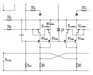
OK. Here is a schematic of what I'm doing. I publish it with reluctance because I'm still in the middle of the fiddle as it were. It was my intention to start a new thread for this mod entitled "AX100J 100W... etc. etc.". I didn't want the project to be posted deep in middle of this thread. So I'm hoping this schematic will pass by largely unnoticed. Only a handful of people seem to be viewing the thread anymore so I may get my wish.
Here's a detailed description of the experiment:
1) I have left the AX100 as unchanged as possible. That means that the operating voltages and bias currents have been preserved as much as possible. All of the changes have been to the input diff pair and the input and feedback networks.
2) I have substituted two 2SJ109BL JFET pairs in place of the original 9610's. Each pair is divided between the plus and minus sides. I wanted to maintain the 20ma overall front end bias and the original CCS. The J109 has about one fourth the transconductance of the 9610 (@10ma). I knew that one J109 wasn't quite enough from watching the efforts of others and I'm hoping that two pairs will do the deed.
For all those people that are scouring the world for these parts it must seem like a really flagrant case of conspicuous consumption to be paralleling these parts. I apologize to you. It should be possible to implement this circuit with matched J74BLs.
3) The input JFETs have been cascoded. There are two reasons for this. First, it limits the power dissipation to roughly 40mW per transistor by limiting the the voltage across the JFETs. Some people like to run their JFETs really hot. I prefer to avoid the blazing Balkan barbeque effect (I guess it's because I don't want to choke on the smoke). Second, the cascodes reduce the tendency toward current hogging in the paralleled JFETs.
4) I have increased the input network resistors to 22.1K from 10K because these are the values I've seen in the PL manuals that have been publicly (if temporarily) released. (i.e. the X2 and X5). The same goes for the MacMillan resistors. The main feedback resistor is scaled up to 475K. But these are just starting points for experimentation. I can easily experiment with lower values by tack soldering resistors onto these parts.
5) I have removed the input capacitors to make more room on the board. The new board has to match the form factor of the old one. I will try tacking the capacitors back in at the end of the project just to see how the performance and sound are affected.
6) The input protection diodes are removed and so are the gate resistors on the diff pairs. One of the benefits of JFETs over MOSFETs.
Anyway that's it for now. If you spot any issues please point them out. The same goes if you think of something worth trying.
I agree with William wholeheartedly by the way. I've built (and bought) lots of audio gear over the years and IMO the pieces with the JFET inputs sounded best. There is just a level of detail and timbrel rightness that I don't hear with bipolar or MOSFET inputs. This is nothing more than one mans opinion. But just look at the enormous trouble people like Nelson Pass, John Curl, and Charles Hansen go to to obtain and use the special Toshiba JFETs they use on the inputs of their products. There is something there.
Regards,
Graeme
Here is the schematic. Ignore the notes in the lower right hand corner. I have not updated them yet.
Attachments
At the risk of being accused of suggesting the use of obsolete parts, why not use a pair of cascoded LU1014s at 100mA bias each for the diff pair ? You can lower the drain resistor to 39R, and still get enough gain, as the transconductance of the LU1014 at 100mA is about 1-2 S.
Or maybe one can ever get the LU1014 to work in triode mode for yet lower current, say 50mA ?
Patrick
Or maybe one can ever get the LU1014 to work in triode mode for yet lower current, say 50mA ?
Patrick
Hi Graeme,
Thankyou for posting in such detail.
As always well thought out!
On point 3 cascoding will help with the issue of additional input capacitance with parrallel pairs.
I will give you design modification a tryout.
To do this I will make a small daughter board (from vero board) probably using the 2SJ74 as the pin out with vero board may be earier to arrange. The 2SJ109 will require less matching but as we know they are few and far between and expensive.
If it is preferred to move this discussion to another thread by all means do so.
I agree a new board is in order but a mini daughter board may not be a bad idea for those who have built their amps.
Send me a message and I try and organise parts for you to try.
Macka
Hi Ian,
My original board is Vero board so making a complete new one is the best plan. It keeps the amps out of service for the minimum amount of time while switching over (or back).
Thank you for the offer of parts but I already have everything I need. I stocked up several years ago on JFETs.
The project has been making little progress since last summer but your posts have caused things to lurch back into motion. I take Nelsons comment above as very positive and encouraging.
One thing I didn't mention above is that I am changing to the tighter version of the diff pair CCS in order to make the absolute offset adjustment pot smoother and easier to deal with.
If you get there before I do please post your results! I'm at least three or four weeks away from light up.
Graeme
gl said:,
The project has been making little progress since last summer but your posts have caused things to lurch back into motion. I take Nelsons comment above as very positive and encouraging.
Graeme
Hi Graeme,
What you are doing is right on the money..apparently.
I should have something to report next weekend..so hold me to it!
Macka
EUVL said:At the risk of being accused of suggesting the use of obsolete parts, why not use a pair of cascoded LU1014s at 100mA bias each for the diff pair ? You can lower the drain resistor to 39R, and still get enough gain, as the transconductance of the LU1014 at 100mA is about 1-2 S.
Or maybe one can ever get the LU1014 to work in triode mode for yet lower current, say 50mA ?
Excellent ideas. You don't necessarily have to cascode the
input stage, but it wouldn't hurt.
Crimestopper's textbook:
For P channel outputs, use the Harris or Fairchild parts.

> You don't necessarily have to cascode the input stage, but it wouldn't hurt.
For two reasons :
1) In my limited experience with the device, it is essier to get a linearised triode characteristics with a smaller Vds, say around 3V.
2) Cascode will reduce miller effect at the input.
> For P channel outputs, use the Harris or Fairchild parts.
How about 2SJ554 (4S at 1A bias) ?
Patrick
Attachments
EUVL said:> 1) In my limited experience with the device, it is essier to get a linearised triode characteristics with a smaller Vds, say around 3V.
2) Cascode will reduce miller effect at the input.
> For P channel outputs, use the Harris or Fairchild parts.
How about 2SJ554 (4S at 1A bias) ?
Correct on all points, and the 2SJ554 ought to work fine.
Hi Ian,
I didn't understand your last post. Did you mean that you are going to start the thread you talked about on your AX100 by next weekend? Or did you mean that you are going to make this proposed JFET enhancement? Please don't risk your new amps on something I haven't even tried myself. I'd feel particularly bad if my musings caused a smoke cloud in Oz.
The schematic was only provided to make a point. It contains errors. For instance the zener in the cascode circuit is backwards. And lots of the reference designators are wrong and don't match the original AX100-01 or the original Aleph-X. They really should in order to be useful here.
I got the project "box" out yesterday and went through my notes and reviewed where the board build was at this point. It turns out I am further along than I thought. I have already made a number of changes. These are:
1) The backwards zener has been fixed.
2) I restored the input resistors, the input gate grounding resistors, and the MacMillan resistors back to 10K. I've also restored the main feedback resistors back to 221K. I just couldn't think of a good enough reason to change these values. I want to fire the amp up with the original parts so that any change produced by substituting the JFETs can be isolated to the extent possible. I have put Vero clips on the board for mounting the MacMillan resistors and the gate grounding resistors so that I can play with these easily AFTER I've given the amps time to burn in and I've gathered some listening time with them. I don't anticipate a lot of improvement with this bit of tinkering.
3) I will continue with the plan to remove the input coupling caps.
4) The tighter CCS range will be substituted as planned.
5) I am conpleting both new boards but I will mod only one amp to start with so that I have a reference in case of trouble.
I will keep you posted if I make any more changes or discover any more errors. I may just be able to light up next weekend myself!
Cheers,
Graeme
Graeme,
I propose to make the Jfet enhancements.
Thanks for the warning but no need.
I made a similar observation about smoke from 16 power fets with Np.
I now feel a lot more relaxed but I think Np makes it look easy.
Apparently the 2 key things are baising the Jfets correctly and getting 4-5 volts across the gates of the fets.
My plan to set up the driver board prior to connecting the power fets to avoid an accident.
I do want to discuss a couple of points with you.
1. How critical is the actually bias of the Jfets? ie the Jfets themsleves to as applied to the overall circuit here.
Is there a sweet spot or are there other issues such as transconductance / gain.?
You mention earlier the J109 has about one fourth the transconductance of the 9610 @10am so i am wondering if some other things come into play in terms of the overall circuit...open loop gain/bandwith and closed loop gain/bandwidth.
Its been a while since I looked at biasing jfets in detail and I intend to read both Jfet Frontier Articles by Borbely shortly.
2. In the current X Aleph you have 10pf compensation capacitor on the feedback resister of 220K.
I notice aftering using my amp for a while now there is some.
e loss of HF details but otherwise a warm well balanced sound.
I am not sure why . Perhaps it could be I have more stray capacitance in my wiring so I was wondering if reducing this to 5pf or less would help matters or do I have problems elsewhere?
I seem to recall Np saying it was a case of trying it early on in the original X Aleph (twisting a pair of wires)
I did try changing the feedback resister to 100K but the balance tonally went to the other extreme.
Macka
Hi Macka,
biasing them is quite simple but depends on the Idss of the used Jfets. If they have a Idss of 10mA you can bias them at around 5-6mA to have the largest possible swing. i did some measurements of the actual voltage swing over the drain resistors and think I´ve mentioned them in my thread (AlephJ-X):
http://www.diyaudio.com/forums/showthread.php?threadid=98763&perpage=25&highlight=&pagenumber=1
Reading the Borbely articles is a good idea!
I`ve used 910R drain resistors for one pair of 2SJ74 with around 9mA Idss.
William
wuffwaff said:Hi Macka,
biasing them is quite simple but depends on the Idss of the used Jfets. If they have a Idss of 10mA you can bias them at around 5-6mA to have the largest possible swing. i did some measurements of the actual voltage swing over the drain resistors and think I´ve mentioned them in my thread (AlephJ-X):
http://www.diyaudio.com/forums/showthread.php?threadid=98763&perpage=25&highlight=&pagenumber=1
Reading the Borbely articles is a good idea!
I`ve used 910R drain resistors for one pair of 2SJ74 with around 9mA Idss.
William
Hi William,
Nice to hear from you.
Thanks for the tip.
I read the 1st article...very interesting.
I guess I will have to set up a jig for those P channel J fets.
Have you been watching the Australian Open?
I am watching Hewitt play the 49th ranked Serb marvle.......no TV sound.......the X 100 playing a nice Jazz Cd I bought at the Blue Note Club in New York after a show......the best of both worlds.
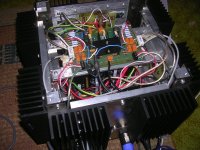
By the way I fixed the frequency thing. It was the way I had the sense and gate wiring arranged in a covered figre 8 pair.
The system seems to be very sensitive capacitance in that regard.
Once I have finalised everything the wiring will be tidy up.
Macka
Attachments
Hi Macka,
no tennis for me.
Getting matched jfets can be a bit difficult. I matched them for identical Idss and Vp but still had difficulties getting them close enough (maybe 25 samples) so I used a 10R pot at the sources.
Current source connected to the wiper so I can set the source resistors for zero offset. Works fine.
William
and yes, a bit of tidying up would be nice
- Status
- This old topic is closed. If you want to reopen this topic, contact a moderator using the "Report Post" button.
- Home
- Amplifiers
- Pass Labs
- AX100 100W Aleph-X Monoblocks