aleph 1.2's to Ax100
Ok, I will install your resistors as shown on the schematic for the bias with a pot in series and slowly adjust it. I think this process is simple enough.
Regarding the 50% current gain, I think I understand ok and I have reread NP's article in Audioxpress on the Aleph current source just to make sure that I am ready. If I take my time I should be ok since I will start this process using a variac and some fuses to limit any circuit malfunctions. More to come when I get back.
What is going on here in SF in October, I will ask my son to attend for me at the show you will be displaying your amp. He works in Silicon Valley in Sunnyvalle.
I am staying near Mountain View. I am not sure where NP's factory is!! Some threads indicate he is located in NAPA Valley running the wine tasting. dave
Hi Dave,
I'm sure Nelson will get a chuckle out of your comment. He's in Foresthill about 150 miles east and somewhat north of San Francisco - and well past Napa.
I'll keep you posted on whether or not I can manage to get to the event. It's only 8 or 9 weeks away and there are already things that have been put on my calendar. Fall is a busy time. I wish they had scheduled this thing for January or February. I'm usually in the mood for a lift during those months.
Graeme
aleph 1.2's to Ax100
GL, I am planning my testing regiemen for the driver boards and I have some questions, I looked briefly through the threads but didn't find (it still could be there) what I was looking for:
1. The 200ohm pot you call U2 I believe is to adjust the current source for the input diff pair to 20ma which puts 10 ma through each device and I should measure 4-5 volts across the 392 ohm resitors R22 & R26. I am hoping these meausrements of dc for each resistor will be very close so out put dc offset will be low. I matched them to the accuracy of my digital meter. Do you if anyone ever trimmed the diff input pair with a small source resistor? I know that can add noise.
2. This also means that the voltage drop across Q4 & Q9 will also be 4-5 volts.
3. NP uses a .047 cap across the collector to emitter of Q3 and Q8 but you did not use these and I can only guess they were for stability at dc and prevent oscillations?
Am I on the right track? dave
aleph 1.2's to Ax100
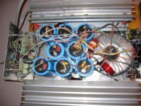
GL and Grey, I am posting some pictures of the conversion project from an Aleph 1.2 to an AX 130+ I think.
The picuture here is my 7 year old aleph 1.2, in disassembling it I found that the cl 60 thermistor to ground was smoked in half but it still read 16 ohms cold, I have no idea what happened.
The cl60 surge thermistor I replaced a few months ago and then bypassed it with a ac relay set for 60sec's to protect it.
This is not an easy project-more pics to follow.
Attachments
aleph 1.2's to Ax100
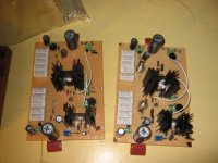
circuit boards with pt to pt wiring:
I mounted the diff input pair to the same heat sink and measured and matched every resistor and fet.
I have to do a continuity and node check on the boards to make sure every thing is hooked up correctly before I put it into the amp.
circuit boards with pt to pt wiring:
I mounted the diff input pair to the same heat sink and measured and matched every resistor and fet.
I have to do a continuity and node check on the boards to make sure every thing is hooked up correctly before I put it into the amp.
Attachments
aleph 1.2's to Ax100
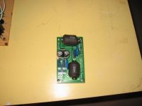
Grey talked me into a dc blocking cap and noise reduction circuit to eliminate any transformer buzzing. The Plitron 2kva torrodials for the Aleph's buzzed like a bees nest hit with a baseball bat.
In the prior picture of the cirucuit boards I installed high quality pots to do the dc bias and set the current source to 50% gain.
Attachments
aleph 1.2's to Ax100
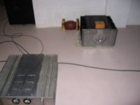
I couldn't resist, my Pass A75 built in 1993 is still bigger than the Pass 350.5 seen in the background. The only dimension the 350.5 is largher is height 9'' to 7". Yes I tried to help NP's bottom line with my first purchase in 15years. It was quite a negotiation for the 350.5 but when DNA evidence dating back to the 15th century proved that the salesman and I were long lost brothers from Scicly he consented to a deal. I of course had to point out that there was one minor scratch on the bottom of the unit and that the shipping box looked like it had been run over with a lift truck entitling me to several thousand dollars in discounts.
dave
Attachments
Hi Dave,
Thank you for posting the photos. It looks like things are coming right along. To answer your questions from 3 or 4 posts back:
1) When the time comes you will be looking at the the absolute and relative offset voltages on the outputs - not at the voltage across the diff pair drain resistors. You might look at these voltages as a first step in troubleshooting if you can't get the outputs to adjust to zero. Just remember that the diff pair CCS adjust pot can swing the output DC over a huge range - like rail to rail - plus it's very sensitive. You need to variac the amp up to where the CCS turns on before you can start making effective adjustments. That means more than 9V across the zener in the CSS.
I am not aware of anyone who has trimmed the diff pair with source resistors in the Aleph-X. I wouldn't bother.
2) Yes.
3) Like you say - sometimes NP uses caps in these locations and sometimes he doesn't. My amps run fine without them.
Yes - you are on the right track.
Cheers,
Graeme
signal grounding for the aleph 1.2 to AX100 project
GL, one of the things with my layout is that it is horizontal and with converting my Aleph to an XA I will have at least 12-15 inches of wire runs from the driver board to the output devices souce resistors and gates. On my Alephs, these are short.
I am wondering if I need to use shielded wire and ground the shield at the driver board and on the open shield end put a picofarad cap to ground to prevent emi/rfi and other assorted nasties.
In my Aleph layout I never experienced any oscillations of the cirucuit but again my wiring is short. In looking through the vent openings on my pass 350.5 NP uses a more vertical arrangement with from what I can see extremely short connections.
I know that fets can have issues with oscillations. What do you think? Once I get this monster wired up, I would hate to have to redo anything. dave
Hi Dave,
Bottom line - I don't know. I'm not there to see what you're seeing. But short wires are definitely the best idea if at all possible. I have a real thing for that as you can see from the pictures at the beginning of this thread.
Check for oscillation when you fire it up.
Graeme
Bottom line - I don't know. I'm not there to see what you're seeing. But short wires are definitely the best idea if at all possible. I have a real thing for that as you can see from the pictures at the beginning of this thread.
Check for oscillation when you fire it up.
Graeme
")
I am very seriously considering journeying to the burning amp event and taking these amplifiers. As of this date there don't appear to be any Aleph-X's going. If anyone out there is going and is interested in hearing them, please let me know. I would appreciate your input. Thank you.
Cheers,
Graeme
Cheers,
Graeme
gl said:I am very seriously considering journeying to the burning amp event and taking these amplifiers. As of this date there don't appear to be any Aleph-X's going. If anyone out there is going and is interested in hearing them, please let me know. I would appreciate your input. Thank you.
Cheers,
Graeme
what you think that amp on main page of Burnin' Amp is ?

Are you asking me to guess? OK, I'll guess.
I think they're Pass Labs X600 clones. Either AR2 designed up his own version of the X600 or he got his hands on a service manual. The only way to find out for sure what they are is to go to the event. In any case they are extremely impressive looking pieces.
Graeme
I think they're Pass Labs X600 clones. Either AR2 designed up his own version of the X600 or he got his hands on a service manual. The only way to find out for sure what they are is to go to the event. In any case they are extremely impressive looking pieces.
Graeme
california dreaming
GL, let me know if you go to the burning amp event? I suppose it is the one in Kali-for-nia (Arnold's pronounciation) near SF. If it is I will try to talk my busy son into visiting for me. I am travelling on business overseas right now but I have modified one bank of output devices and installed the dc/noise filter and new xformer.
I also did a continuity test on all the nodes on the driver boards.
Now I have to figure out how to set up my signal generator into the balanced inputs. I might have to short the -input to ground for testing. I will be back in early October to finish. dave
Can you please help me here. I am a beginner and want to set the Bias. Where should i measure the Voltage and where should it be 0,47-0,5 Volt for a 100w version?
Between the yellow spots i see 0.02 Volt and between the blue ones 17.2Volts.
Between the yellow spots i see 0.02 Volt and between the blue ones 17.2Volts.
An externally hosted image should be here but it was not working when we last tested it.
- Status
- This old topic is closed. If you want to reopen this topic, contact a moderator using the "Report Post" button.
- Home
- Amplifiers
- Pass Labs
- AX100 100W Aleph-X Monoblocks