How is it going?
Well, i did a try using a verobaord.
I first mounted the toshibas 1302/3281 and then the sankens.
Since i ve only a few toshibas pairs, i left the darlingtons and
added a LR circuit consisting of a 1uH inductance and 1 ohm
resistor as the amp is powering a friend s keyboards at home
using a pair of yamaha NS10 speakers.
Myself , i use exactly the same design safe that the power
trannies are Hitachi 2SJ48/2SK133 and with a slightly higher
supply voltage..
In listening tests, i must aknowledge that there was no
blatant difference, although the mosfets seems to be a
little more clinical , not to say agressive..
It has perhaps to do with the compensation schemes which
are different on the two amps.
The speakers that were used for comparison are my old faithful
Quested H108 , a pair of near field two way studio monitors..
NS10's, quested H108
 Wahab you are a perfectionist and take your designs very seriously, step up on the speakers and come back again , we need to know what this thing really sounds like,
 very interesting design.....
NS10's, quested H108
The Yamaha, i also don t like them, but what s wrong
with the H108s ?..
The Yamaha, i also don t like them, but what s wrong
with the H108s ?..
Okay the H108's are "OK" morel tweeter is good enuff for top end detail and is an easy load for your amplifier .
What kind of power are you thinking of with this design ?
I think it´s a VIFA, Dunlavy used that tweeter in very expensive speakers.
Nah ..... Morel , better than vifa .....
Okay the H108's are "OK" morel tweeter is good enuff for top end detail and is an easy load for your amplifier .
What kind of power are you thinking of with this design ?
The amp that is in this thread?..About 50W rms/8 ohm..
More is possible, but i retained something that would be
not to complexe , so i settled for this range of power
that is enough for the majority of audiophiles..
As already mentionned, i use a Mosfet version that is
2 x 100W or.....2 X 8W , since i use two different power supplies,
depending of the needs..
Last edited:
I am using this topology (but with current sources in the LTP's and cascodes in the VAS) and get >250W into 8 ohms and >400W into 4 Ohms as measued on an AP. Unfortunately, the transformer is wound for 120/240VAC and the mains voltage here is 100VAC, otherwise it would be C. 300W and 500W respectively. I am using 5 pairs 21193 and 21194 per channel.
Yes, this topology can deliver the juice 'Big Time'.
Great looking little amp BTW Wahab!
Yes, this topology can deliver the juice 'Big Time'.
Great looking little amp BTW Wahab!
The amp that is in this thread?..About 50W rms/8 ohm..
More is possible, but i retained something that would be
not to complexe , so i settled for this range of power
that is enough for the majority of audiophiles..
As already mentionned, i use a Mosfet version that is
2 x 100W or.....2 X 8W , since i use two different power supplies,
depending of the needs..
Interesting , i have never owned such a small amplifier , i would be interested in 50 w@8 if it doubles down to 1 ohm ...
I'm getting ready to finish my PSU , 28 V +/- with 1000KVA trannies /side and 240K uf caps, it will be a separate chassis and allow me to try out different amplfiers ..
How is the sound ?
regards,
Last edited:
I am using this topology (but with current sources in the LTP's and cascodes in the VAS) and get >250W into 8 ohms and >400W into 4 Ohms as measued on an AP. Unfortunately, the transformer is wound for 120/240VAC and the mains voltage here is 100VAC, otherwise it would be C. 300W and 500W respectively. I am using 5 pairs 21193 and 21194 per channel.
Yes, this topology can deliver the juice 'Big Time'.
Great looking little amp BTW Wahab!
Thanks, Bonsai
Did you make a try with the like of 1302/3281 or 1943/5200 ?
Pavel said that using these fast devices reduced greatly the THD
compared wih the 21193/21194.
Interesting , i have never owned such a small amplifier , i would be interested in 50 w@8 if it doubles down to 1 ohm ...
I'm getting ready to finish my PSU , 28 V +/- with 1000KVA trannies /side and 240K uf caps, it will be a separate chassis and allow me to try out different amplfiers ..
How is the sound ?
regards,
No surprise with the sound, it s tight and balanced, as always
with this kind of topology, provided no fatal mistake was done
in the design.
In Bonsai s words, the juice is sweet and smooth..
That said, if you want 1 ohm load capability, it would be necessary
to add one , or even two pairs of power devices..
A medium power amp can sound as good as one that is way more
powerfull, provided it is designed with the same requirements.
Often, very powerfull amps are branded better than mid power ones,
but this comes mainly from the beefed supply and power stage,
which are unfortunately often anemic in lower power versions...
Thanks, Bonsai
Did you make a try with the like of 1302/3281 or 1943/5200 ?
Pavel said that using these fast devices reduced greatly the THD
compared wih the 21193/21194.
Wahab, no, I have not tried those yet - I will on my next iteration.
Value for the zener feed resistor
Hi AKSA, Wahab,
I like simple amp circuit and I have done the schematic & layout on KiCad. I have attached a zip file with the schema & layout in word format.
I used AKSA's schema as a base as I could not read the component values on Wahab's files.
I have a few questions with regards to the parts values & choice. I will use the component designator in my schema.
(1) The original zener for D1 & D2 are 18V, then what value should I use for R10 & R14 (zener feed resisters)?
(2) I notices that 1K was used for R4 & R9 in Wahab's schema, these two resisters are replaced with a link in AKSA's schema. Which is correct?
(3) I have a couple of 4.7uF Wima polyester film cap which I intend to use for this build. Do I need change any of input filter network like R1, R2 & C3?
(4) I have some BF469 & BF470 in my parts bin, can I use them for VAS (Q5 & Q6)?
(5) I will use a 28V AC transformer that will give about 39V DC, do I need to change anything?
Thanks & regards, Stanley
Hi Wahab,
I have done the simulations and found excellent results, here:
Gain 26.8dB, -1dB point at 282KHz
Loop gain 48dB at 1KHz
Unity Loop Gain -63 degrees at 1.6MHz (WOW!!)
-3dB dominant pole at 4.3KHz
Phase shift at 100KHz is -13.8 degrees
These are good results, although phase shift is a little high. I have substituted A1360/C3423 for the VAS devices, A1837/C4793 for the drivers, and 4148s for the diode string. I have only 15V zeners, not 18V, so the feed resistor is 3K9. This all gives around 420mA quiescent, which is too high, very deep AB, but the results are very good with very low distortion: -108dB at 20KHz for H5, not bad at all! A pot across one of the diodes would reduce this bias level to a more reasonably 80mA or so..... then I will take more measurements.
Thank you for sharing this circuit,
Hugh
Hi AKSA, Wahab,
I like simple amp circuit and I have done the schematic & layout on KiCad. I have attached a zip file with the schema & layout in word format.
I used AKSA's schema as a base as I could not read the component values on Wahab's files.
I have a few questions with regards to the parts values & choice. I will use the component designator in my schema.
(1) The original zener for D1 & D2 are 18V, then what value should I use for R10 & R14 (zener feed resisters)?
(2) I notices that 1K was used for R4 & R9 in Wahab's schema, these two resisters are replaced with a link in AKSA's schema. Which is correct?
(3) I have a couple of 4.7uF Wima polyester film cap which I intend to use for this build. Do I need change any of input filter network like R1, R2 & C3?
(4) I have some BF469 & BF470 in my parts bin, can I use them for VAS (Q5 & Q6)?
(5) I will use a 28V AC transformer that will give about 39V DC, do I need to change anything?
Thanks & regards, Stanley
Attachments
Stanley, answers:
1. 4k7
2. Link. The resistors do not contribute to diff pair balance at all; they are superfluous.
3. Nothing you would notice.
4. Yes, though the best devices for this are Toshiba 2SC3423 and 2SA1360. These devices are possibly the significant choices for the sound quality in the amp.
5. Should be fine.
Hope this heps,
Hugh
AWB-50 schematics
Thanks Hugh,
I probably build the amp using components from my parts bin. I got most of the small polyester (green) caps and NPO ceramic for the C11.
If it goes well, I may upgrade some of the transistors with the Toshiba & capacitors with silver mica & etc.
Another question:
Are the C6 & C8 (270pF) critical to the sonic?
I managed to import the schematics into PDF and KiCad is quite easy to use, it took me two days to get the hang of it.
Cheers, Stanley
Attachments
Last edited:
Are the C6 & C8 (270pF) critical to the sonic?
Yes, Stanley,
Possibly THE most crucial caps on the entire schematic. They are lag compensation caps, dimensioning and quality are both critical. Use silver mica.
Cheers,
Hugh
One channel is working
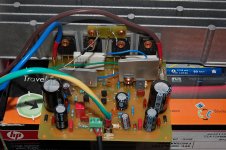
I have made the PCB and build one channel with components from my parts bin.
VAS - BF469 & BF470 (Philips)
Driver - 2SB649A & 2SD669A (Hitachi)
OPT - 2SA1490 & 2SC3854 (Sanken)
Bias Diodes - 1N4936
The 18V zeners have 18.4V forward voltage drop, I have to use four pieces of 1N4936 diodes to get about 100mA across each emitter resisters (1N4148 & 1N4004 diodes gave too high bias current). I am still experimenting with the types & mounting of thermal-compensation diodes.
The Amp is quiet (no hum or hiss) and it is clear with bias towards the higher frequencies. Violin & jazz sound good on this amp.
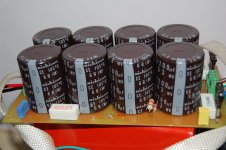
The initial test was done with only 6600uF filter capacitance per rail and the sound was quite thin. I then increased the filter capacitance to 32800uF per rail & the sound become more balanced.
I will build the second channel with 10uF DC blocking cap, silver mica caps & Toshiba VAS.
- Stanley
I have made the PCB and build one channel with components from my parts bin.
VAS - BF469 & BF470 (Philips)
Driver - 2SB649A & 2SD669A (Hitachi)
OPT - 2SA1490 & 2SC3854 (Sanken)
Bias Diodes - 1N4936
The 18V zeners have 18.4V forward voltage drop, I have to use four pieces of 1N4936 diodes to get about 100mA across each emitter resisters (1N4148 & 1N4004 diodes gave too high bias current). I am still experimenting with the types & mounting of thermal-compensation diodes.
The Amp is quiet (no hum or hiss) and it is clear with bias towards the higher frequencies. Violin & jazz sound good on this amp.
The initial test was done with only 6600uF filter capacitance per rail and the sound was quite thin. I then increased the filter capacitance to 32800uF per rail & the sound become more balanced.
I will build the second channel with 10uF DC blocking cap, silver mica caps & Toshiba VAS.
- Stanley
Attachments
- Status
- This old topic is closed. If you want to reopen this topic, contact a moderator using the "Report Post" button.
- Home
- Amplifiers
- Solid State
- awb50 ,a simple power amp