There's something else I'd like some thoughts on.
What are the signal levels you'd expect to input to the ar? For instance, if you want to check a 300W/8ohms power amp at full power, you'd have almost 50V RMS input signal. I would think that's about the max people would use.
This is not the same as the max input level without breaking it - in my current prototype you can easily input 100 or 120V RMS and nothing will break.
But for max input level for outputting the 'sweet spot' voltage to the soundcard, it seems to me a 50V RMS max spec would be more than enough.
Thoughts?
Jan
@Patrick: for the kV amp I'll have to make do with a custom attenuator ...
")
When will you be in NL again?
Jan
One range Must be 1v = 0dbV. All other ranges could be multiples/division from that.
I would be ok with 50v rms Spec. !00 better, though. I have a conserv. rated analog mono amp of 450W 8 Ohms. But.... you know....
Never mind about the M2's dig amp from Crown at 5000W/chnl.
THx-RNMarsh
I would be ok with 50v rms Spec. !00 better, though. I have a conserv. rated analog mono amp of 450W 8 Ohms. But.... you know....
Never mind about the M2's dig amp from Crown at 5000W/chnl.
THx-RNMarsh
Last edited:
Going past 100V is a challenge. Most analyzers stop at 100 V or so (including AP). The Boonton is good for 300V, making the input protection more challenging. The Keithley 2015-2016 is your best option for the high power amps at 750V. Its residual is in the .003% range and harmonic analysis seems to need the -p version. 2015's can be had on eBay for $350 from Parts Express who bought a lot of them.
5KW of load resistor is another "hot" challenge as is the 220V 30A service to support that power.
I don't think Jan needs to support all the edge cases. 100V to 100 KHz should be good enough for anyone. My goal is to check the 100V @ 100 KHz later this week. I need to shuffle the big amp over to test it.
The thing is, a 40dB attenuator, with good accuracy and wide bandwidth (200kHz) is relatively easy to make and can be adjusted for flat response without expensive test equipment. If you settle for an output sweet spot of 1V, this gives you 100V input level in linear operation, and that is what the AR has been designed for, with an overload margin to 150V. All RMS.
But. If you want an output sweet spot of say 0.3V, the 40dB gives you a max input level of just 30V. So you then have a redesign or some additional attenuation which is always detrimental. A transparent, wideband 60dB attenuator that can be adjusted in a typical DIY shack is no-go.
Need to do some heavy thinking here.
@Demian: I have a pair of 2015D's. Best kept secret in the diy world!
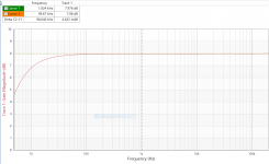
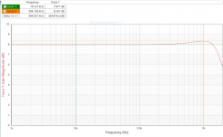
To the graphs: note the magnitude delta's in the cursor readout boxes..
Jan
But. If you want an output sweet spot of say 0.3V, the 40dB gives you a max input level of just 30V. So you then have a redesign or some additional attenuation which is always detrimental. A transparent, wideband 60dB attenuator that can be adjusted in a typical DIY shack is no-go.
Need to do some heavy thinking here.
@Demian: I have a pair of 2015D's. Best kept secret in the diy world!
To the graphs: note the magnitude delta's in the cursor readout boxes..
Jan
Attachments
Last edited:
One range Must be 1v = 0dbV. All other ranges could be multiples/division from that.
snip snip
THx-RNMarsh
dBV is an absolute number meaning that 0 dBV = 1volt.
"At this point the AR displays the attenuation/gain in dB as a dimensionless ratio." (see Jan's post #104) The ar does not measure or display level (voltage) or calculate dBV.
Come to think of it the AR output Voltage 1.0V, 0.5V or 0.25V is only to match the sweet spot of the sound card input. ARTA will calculate the FFT on a dBV scale if the AR input level and the attenuation/gain are known. The AR output voltage is included in the calculation of the displayed dB's on the face of the AR.
DT
The Test instrument has to also measure at the specified output voltage of the DUT. For line level, that is usually (consumer) 1 and 2v. Pro, higher.
THx-RNMarsh
RNMarsh,
Exactly, that is the point!
A sound card with an AR interface attached is not an AP2722, nor is it intended to be.
The AR does not measure the output voltage of the DUT even if we say it has to.
DT
RNMarsh,
Exactly, that is the point!
A sound card with an AR interface attached is not an AP2722, nor is it intended to be.
The AR does not measure the output voltage of the DUT even if we say it has to.
DT
The AR displays the level being send to the soundcard, displays the attenuation setting, and from that calculates and displays the input voltage to the AR, which is of course the DUT output.
The level indicated going into the soundcard is approximate and the soundcard with its 24 bit ADC is much more accurate so the ARTA or whatever level should be considered the true level. But it gives you a pretty good indication what's going on level wise.
Jan
Last edited:
I would fix the ranging to 3v and a passive attenuator on the output to match the soundcard.
Most Opamps give their best performance around 3v.
Sent from my LG-H811 using Tapatalk
That is my current thinking. I could implement a couple of jumper-selected settings.
There's one issue to solve: a passive atten loads down the output amplifier. So you want to keep the passive atten impedance level highish. But that makes the output impedance higher and thus may give attenuation by the soundcard input impedance which is not accounted for.
As an example, a passive atten with say 1k load impedance and 6dB atten. has an output impedance of 250 ohms. Is that acceptable?
A rock and a hard place.
Jan
The Test instrument has to also measure at the specified output voltage of the DUT. For line level, that is usually (consumer) 1 and 2v. Pro, higher.
THx-RNMarsh
Richard, if I understand you correctly, that is implied in the auto level setting. The AR will automagically range to 0dB with a 1V input (when set for a sweet spot of 1V to the soundcard).
Jan
Not exactly feature creep, but it can't be the jeep of the test instrument world. Output levels of 0.316 and 1 volt should make everyone happy. The DUT will have level controls and for low level equipment you would be using another attenuator anyway. Example, reverse RIAA and a non-eq'd attenuator for mic levels. I guess you might want to use a 2V level to drive some amplifiers.
As for high impedance attenuators, there will be some HF correction required. Set for some impedance level, maybe assume 10K for amplifiers and other sound equipment. That covers early standards and the 50K current standard is easy enough to correct for. Of course, you could monitor the actual output level and adjust the gain to correct for impedance on the load side.
There should be a way to break this log jam, and anything is better than nothing as far as this equipment is concerned. Best effort counts for me Jan.
So, should we expect a companion meter bridge for this, or will it be built in? Plasma meters please.
-Chris
Hi Jack,
Power bandwidth for one, and any other funny things that can happen as the current is increased. I expect that more hobbyists will be looking at their own work instead of measuring commercially available amplifiers. That means that just about anything can happen in the way of weirdness.
-Chris
Power bandwidth for one, and any other funny things that can happen as the current is increased. I expect that more hobbyists will be looking at their own work instead of measuring commercially available amplifiers. That means that just about anything can happen in the way of weirdness.
-Chris
That is my current thinking. I could implement a couple of jumper-selected settings.
There's one issue to solve: a passive atten loads down the output amplifier. So you want to keep the passive atten impedance level highish. But that makes the output impedance higher and thus may give attenuation by the soundcard input impedance which is not accounted for.
As an example, a passive atten with say 1k load impedance and 6dB atten. has an output impedance of 250 ohms. Is that acceptable?
A rock and a hard place.
Jan
For the sound cards this would be used with 250 Ohms should be fine. I test them with 600 Ohms sources. Even mike inputs are hi-z on these to talk to ECM mikes.
- Home
- Design & Build
- Equipment & Tools
- Autoranger for soundcards