Just curious, how is the AR input protection addressed? At these levels, simple diode protection is a no go, due to the nonlinear capacitance, even 2pF diodes would not let the THD go under -90...-95dB (don't ask me how I know). There is a technique of nulling (bootstraping) the protection diodes, but it is not perfect, the nulling depends on the source impedance.
I can't speak for Jan, but I assume you've tried BAV199? I don't have any measurements in front of me, but I'm pretty sure I've seen better than -100 with BAV199.
Another part that I've seen referenced is a bridge actually, Infineon BGX50A. It is now EOL, though.
Another part that I've seen referenced is a bridge actually, Infineon BGX50A. It is now EOL, though.
Last edited:
BAV99 is 2pF and is a no go, as is. In bridge (cancellation) it would work, but probably needs sorting. I used successfully this chip https://www.diodes.com/assets/Datasheets/ds30158.pdf, diodes are also 2pF but, being 99.9% from the same wafer, matching is pretty much already done. Was able to tune this down to -120dB for a fixed load impedance. Current limiting was by high voltage depletion mosfets.
I think I've read somewhere about the late APs having some sort of automatic input stage protection distortion compensation (requires at least adjusting a resistor on the fly) but I have never seen a schematic.
I think I've read somewhere about the late APs having some sort of automatic input stage protection distortion compensation (requires at least adjusting a resistor on the fly) but I have never seen a schematic.
You might investigate RF PIN diodes--- they have very low capacitance and also low leakage I believe, though that data is more obscure.
Infineon BAR63-03WE6433
https://4donline.ihs.com/images/Vip...4-1.pdf?hkey=52A5661711E402568146F3353EA87419
Infineon BAR63-03WE6433
https://4donline.ihs.com/images/Vip...4-1.pdf?hkey=52A5661711E402568146F3353EA87419
The leakage can be important, too. That Schottky array is quite a bit leakier than a BAV199.
Works fine in bridge configuration, reverse currents cancel as well. You may worry abut temperature drift, but this is a non issue here, it is not intended for military or space operations
 .
.You might investigate RF PIN diodes--- they have very low capacitance and also low leakage I believe, though that data is more obscure.
Infineon BAR63-03WE6433
https://4donline.ihs.com/images/Vip...4-1.pdf?hkey=52A5661711E402568146F3353EA87419
These could work too... never tried them myself.
I am using pre-biased FDH300 diodes. The capacity is not so much of an issue as long as it is constant with level.
Can you provide some details abut this "pre-biased diodes" protection setup? The FDH300 are 6pF diodes, worse than 1N4148 (which are 4pF) and the capacitance variation with input signal is really critical, even for 2pF diodes.
Looking at the better 1N4148, if such a diode would be reverse biased at 10V, it would have (according to the datasheet) about 0.82pF. The nonlinear current resulting from the capacitance variation (which would be, also from the datasheet, about 0.05pF, which is, at 1KHz, a reactance of 3200Mohm) is, for a 10V input, 3nA. This current drops a nonlinear voltage on the input current limiting resistor (say, 1kohm) of 3uV. This nonlinear voltage is effectively in series with the measured input voltage and appears as odd harmonic distortion (since it occurs twice every sine cycle). 3uV of second harmonic means your overall THD is already down to -110dB, before considering any second order effects like diode mismatches.
At 10KHz, since the parasitic capacitance variation reactance decreases 10 times, the nonlinear current increases to 30nA leading to an overall THD of about -90dB, which is quite bad. And the FDH300 being 6pF would likely be even worse (datasheet has no reverse capacitance variation information).
Last edited:
1N4149 is indeed 2pF. If one wants to make the input protection transparent (no distortion added) in the entire audio band that is, according to my experience, not good enough (just halve the number I posted above). PIN diodes, as indicated by BSST above, would probably do well (never tried myself, I will ASAP). Bootstrapping techniques, using diode quads, cancelling the effect of non linear capacitance, is what I successfully tried at -120dB, but is also not perfect.
Wasn't it Victor (Vicnic)?Someone from Tallinn, Estonia wanted an autoranger from me but I can't find back the name.
1N4149 is indeed 2pF. If one wants to make the input protection transparent (no distortion added) in the entire audio band that is, according to my experience, not good enough (just halve the number I posted above). PIN diodes, as indicated by BSST above, would probably do well (never tried myself, I will ASAP). Bootstrapping techniques, using diode quads, cancelling the effect of non linear capacitance, is what I successfully tried at -120dB, but is also not perfect.
There are tricks using the gate-source of a Jfet as a low leakage diode. However those circuits are so fragile that they don't offer much protection. Below is the bootstrap used the Shibasoku that is good to well below -130 dB. You could build a variation with a buffer connected to the inverting input of the input opamp to drive the bootstrap caps.
The input C variation is a major limitation in distortion analyzers. With a low Z source you don't see the effect, however from a 10K source it can be obvious. The circuit below goes to great extents to eliminate those effects with the bootstrapped cascoded Jfets as followers into a bipolar pair.
Attachments

Protection is hard to make so that the impact is zero.
A much better approach would be to make the front end overload survivable, obviating the need for protection.
The other aspect is protection of the soundcard or whatever equipment you feed with the analyzer. In the latest autoranger, the output protection, towards the sound card, can be disabled by removing a jumper. That's when you get to -150dB territory. That makes sense as there are soundcards that can survive the AR max output, 10Vrms, without any measures.
Jan
Wasn't it Victor (Vicnic)?
No, but it has been resolved. Thanks for asking.
Jan
Protection is hard to make so that the impact is zero.
A much better approach would be to make the front end overload survivable, obviating the need for protection.
The other aspect is protection of the soundcard or whatever equipment you feed with the analyzer. In the latest autoranger, the output protection, towards the sound card, can be disabled by removing a jumper. That's when you get to -150dB territory. That makes sense as there are soundcards that can survive the AR max output, 10Vrms, without any measures.
Jan
I understand if you don’t want to disclose, but are you using a circuit like the depletion mode current limiters with 2x LND150 or similar to handle overload?
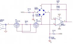
Attached is the setup I experimented with; the idea was from an old EDN Design Idea, with the comment it needs optimization for any practical implementation:
- The Zener diodes need to be forward biased for the works condition (input current is the depletion mosfets saturation current, here about 2mA, if memory serves)
- The Zener voltage needs to be chosen so that the diodes reverse capacitance is in a region with an as much as possible minimum variation, while not pushing it far enough to increase the reverse current.
- The op amp feedback resistor needs to be optimized for a specific value for the source impedance (I used the standard 600ohm).
- The op amp feedback capacitor needs to be optimized for an as much as possible flat response for the distortions vs. frequency, and is specific for each op amp.
With the values in the attached schematic I was able to get a THD anywhere between -127dB and -140dB. This setup cancels both the distortions caused by the reverse capacitance and reverse currents of the diodes, but it needs a diode quad (which are 99% already matched; using individual diodes without matching will not work as expected.
I will try the same setup with the above indicated dual PIN diodes and see if I can get the same distortion numbers, or at least a wider range of source impedance for some -130dB THD or better.
Attachments
Last edited:
There are tricks using the gate-source of a Jfet as a low leakage diode. However those circuits are so fragile that they don't offer much protection. Below is the bootstrap used the Shibasoku that is good to well below -130 dB. You could build a variation with a buffer connected to the inverting input of the input opamp to drive the bootstrap caps.
The input C variation is a major limitation in distortion analyzers. With a low Z source you don't see the effect, however from a 10K source it can be obvious. The circuit below goes to great extents to eliminate those effects with the bootstrapped cascoded Jfets as followers into a bipolar pair.
I know the approach (the diodes are AC bootstrapped with a copy of the input signal) and, to my experience, it works fine as long as you can get dual matched jfets (which are not exactly available today, other than the LSK389). Otherwise, the common mode distortions will dominate. I don't know how to apply the same principle to an op amp, it might be possible, but would be certainly more complicated and dubiously better than the bridge distortion cancellation above.
- Home
- Design & Build
- Equipment & Tools
- Autoranger for soundcards