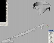
For aesthetic reasons (I'm a grad student in art and technology at Ohio State, so aesthetics is right up there in the scale of things), I am trying to design an 11-sided horn, rougly based on the Edison "morning glory" style horns used in his drum and disc playes of the early 1900's.
I was able to design the horn quite easily by lofting polygons in Autocad's Mechanical Desktop. Now, for the life of me, I cannot figure out how to 'unfold' the model into its 11 constituent components, in order to print cutting patterns. I need to flatten the 3D/curved sides into 2D/flat print space.
Not sure what material I will use to actually make the horn yet, or what size- at the moment it is these cutting patterns I am after. Does anyone have any idea about how to go about this? I am aware of SPI's 'Sheetmetal' plugin but cannot afford this.
Any help you can provide to this newbie horn-maker is much appreciated!
Daniel
I sympathise - iin college when I built a large horn (the Claw)
I managed to pull credits for it from 3 departments. One of them
was a programming class (Fortran!) in which I computed all the
cut pieces for a smooth curve with only 4 sides. I got the credits,
but the results didn't quite fit.
Try Excel.
I managed to pull credits for it from 3 departments. One of them
was a programming class (Fortran!) in which I computed all the
cut pieces for a smooth curve with only 4 sides. I got the credits,
but the results didn't quite fit.
Try Excel.
First, draw the horn profile that the center lines of all the sides will have in 2D. Now break up the profile into segments (ie, divide it every inch or whatever increment is appropriate). Draw the polygon that corresponds to the cross section of the horn at each break point. Now 'list' each curve segment. This is the length down the centerline of the unfolded piece that each segment takes up. Now, start at one end, draw a line equal to the length of one of the sides of the polygon at that point in the horn, and draw a line perpendicular equal to the length of the profile curve for that segment. Keep repeating that until you reach the other end of the horn. Now connect all the endpoints of the lines with a polyline (pline) to get the shape of the individual piece. You can then do a 'pedit' and select to fit the polyline.
http://ldsg.snippets.org/HORNS/images/4way/500hz.jpg
Hth,
John
http://ldsg.snippets.org/HORNS/images/4way/500hz.jpg
Hth,
John
You can have great success with the excellent and affordable Rhinoceros surface modeller [http://www.rhino3d.com]. It is very friendly especially for AutoCAD users. A working trial version is available for free download from their website, and as a student you will be eligible for the student price if you find that you need it beyond the trial period.
It WILL do exactly what you wish to achieve, the relevant command is 'Unroll Developable Surface'. Rhino will open your AutoCAD files directly, and you will either use the acad surfaces directly, or more likely, reference them to [quickly and easily] construct new surfaces, which you can unroll flat if they're not compound curved.
I'd offer to flatten it for you but I wouldn't get to it very soon, as I'm swamped with things to do. Will be happy to answer questions.
Attachments
Large is good. Have a look at Bill's gallery over at audioasylum, see the red horn....
http://gallery.audioasylum.com/cgi/view.mpl?UserImages=21168
http://gallery.audioasylum.com/cgi/view.mpl?UserImages=21168
al finished
Just a note of thanks for the help I got from this post. The art project that this horn was for has been getting a lot of international attention-- it was translated into Russian the other day, and there was an article in Wired News Online. Special thanks to BZdang, for his help. Strangely, he hails from Pickering, Ontario, where I grew up! Now that's kharma.
I ended up doing the following to build the horn, in a slow and painful process:
- Rhino for the design
- Unrolled one side of horn in Rhino and printed it as a full-size template
- Cut sides from bookbinder's 'Davey Board'.
- Glued sides together with hot glue manually ( not reccomended)
- Applied one coat of West Systems epoxy to inside areas, but not seams
- Sanded outside seams
- Applied West eopxy and three layers fiberglass, 8oz
- Many many coats of West epoxy inside and outside to finish, then lots of precious West 410 filler. Sand. Repeat. Sand. Repeat. Repeat again.
- Used a grey plastic electrical fitting for throat connection to compression driver
- Spray painted with gun and Zinsser water-based primer, then finished with One-Shot
brand enamel, two coats and a final 60% pigmented clear coat to give the paint more glossy depth.
Obviously it's not an exponential design-- the acoustic quality is not ideal, but that wasn't the point to begin with- the look of the thing was the most important consideration.
Check out the pictures:
One Free Minute Website: http://www.onefreeminute.net
More pictures: http://www.accad.osu.edu/~djolliff/isd/isd.htm
This board was terrifically helpful in figuring out how to make this thing!
many thanks
Daniel
Terminalcity,
I don't think autocad can unfold anything. Solidworks and Inventor can if the surfaces are flat.
There is a 3D surface modeling program kind of like Rhino called Pilot3D. But with the Pilot3D demo version you can actually use it for 23 saves or imports. You can make an iges file of your model if AutoCAD can do this and import the surface files into Pilot3D demo. Then you can make a flat pattern out of any of the surfaces. And save these 2D patterns as a DXF file. There is a tutorial on the website that shows you how.
Good Luck
Hezz
- Status
- This old topic is closed. If you want to reopen this topic, contact a moderator using the "Report Post" button.
- Home
- Loudspeakers
- Multi-Way
- Autocad for 11-sided horn design?