Just short the caps with jumpers. If you will get undistorted signal, it means you can probably operate the DAC without those caps. Also, you might prefer the sound with the caps in place. The performance is largely dependant on output stage of your transport.
I must have mixed up the caps with ferites. You need two OsCons and two ferrites. I will send you one more OsCon")
I must have mixed up the caps with ferites. You need two OsCons and two ferrites. I will send you one more OsCon
Stabist said:And you get nickel as a kind of color or ???
Yes, the nickel coating is like grey paint, additionally, it is conductive.
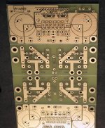
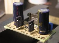
Starting last week, a new LM4780 board is being shipped with the kits. The price didn't change yet, and will be the same untill weekend's over, after that it increases to $25/board.
The main upgrade here is improvement in PS section, so more options, including snubber, can be implemented. The idea is the same as with my LM3875 board, which I described here: http://www.diyaudio.com/forums/showthread.php?postid=584429#post584429
Also the amp section is more flexible now, allowing to use all 3 possible conigurations: stereo, bridged and parallel.
Attachments
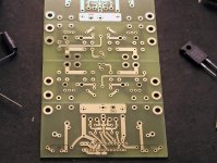
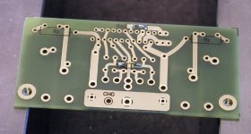
Here's a pic of a stereo setup. Input and output (for each channel) are marked by IN and OUT (in a same outline), SG is for signal ground connection. There are two output ground (OG) hookup points (one for each channel).
The resistors values are as follows:
R3/R5 680R
R0/R4 22k
R6/R7 1k (lower value, down to 200R can be used instead)
R1/R2 22k
No output resistors (0.1R) are used with stereo setup. Same configuration applies to bridge setup, as long as balanced source is connected.
One board allows two separate stereo applications ( which can be suitable for bi amping) and one stereo bridged application.
I will be able to supply 1/2 of the main board only as well (for single stereo application).
Attachments
In order to tie both inputs together (before 1k resistors) a jumper needs to be installed, as pictured.
Also notice, that Rm is SMD resistor. So far, the miniature resistors were supplied for this location (10k), but I might switch to SMD in a future.
Also notice, that Rm is SMD resistor. So far, the miniature resistors were supplied for this location (10k), but I might switch to SMD in a future.
Attachments
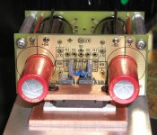
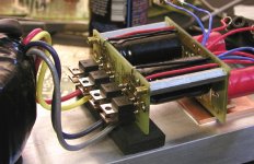
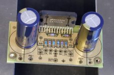
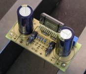
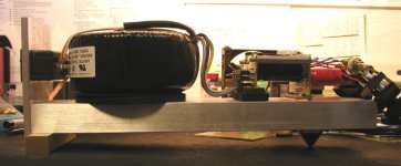
A very simple chassis can be built using minimum skills and resources. The main structural support is provided by 1 x 3 flat bar, about 12" long. There is another small bar in a back, creating footing and a single cone in front ( directly under the chip location). A flat piece of aluminum creates rear panel, where power module (with a switch and fuse) is installed. A similar panel in front (I didn't install it yet), supports input and output jacks.
I didn't notice any hum or interferences with that type of open design chassis, and the sound is very pure without the veil and coloration that more fancy builds impose.
I didn't notice any hum or interferences with that type of open design chassis, and the sound is very pure without the veil and coloration that more fancy builds impose.
Attachments
Peter,
I have a problem
I put in one set of the bridge diodes in backwards.
It was the set used for the analog V+, so I at least blew up the surface mount regulator.
Right now, it only looks like the regulator attached to the 75179 is working right, it puts out 5V.
The two regulators connected to the 8412 are putting out around 8V?
I will double check this later, but that is what I found a little while ago.
At least I did not install any IC's, only passives and the regulators. Also, fortunately, those blackgates are bipolar, so I did not hurt them.
Randy
Check what it's written on the other 2 regulators. I'm pretty sure I supplied 5V type, but you never know. Normally, it should be 5V even without chip mounted.
You might had also blew the diode, so check the voltage after 20R resistors. You should be getting around 11V there (before regulators). Tell me which parts need replacing and I will send them to you.
You might had also blew the diode, so check the voltage after 20R resistors. You should be getting around 11V there (before regulators). Tell me which parts need replacing and I will send them to you.
Peter Daniel said:Check what it's written on the other 2 regulators. I'm pretty sure I supplied 5V type, but you never know. Normally, it should be 5V even without chip mounted.
You might had also blew the diode, so check the voltage after 20R resistors. You should be getting around 11V there (before regulators). Tell me which parts need replacing and I will send them to you.
Hi Peter
Thanks for the support.
I checked the input voltage to the regs, it was around 12V.
I just remembered, U1 (which works) has the output cap installed, but U2 and U3 (don't work) do not have the output caps installed yet, I can't install those until I install the 8412. I think the regs want some output capacitance, so I may take a chance and install the 8412, then install the output caps, and see if U2 and U3 output 5V.
Randy
Peter Daniel said:You can always install the caps temporarily, in the CS8412 holes. You don't even have to solder them, just make sure the pins are in contact with through hole plating.
Hi Peter,
I did not want to use the BG's, but I dug up an old cap, and tried it. Those regs work much better with a cap on the output.
Everything seems to work fine. The three regs each put out a little over 5V, and the SM reg puts out about 7.9V. I remember reading that you thought this DAC sounds better if you give it a little under 8V, which is the max voltage it takes.
There are a couple of "tricks" that took me a little to figure out. One was having to cut the 4 end pins off the 8412, but I looked at a picture you posted to figure that out.
The other one, which I should have figured out, was I needed to solder two caps to the 8412 pins. I should have done it before I installed the 8412, but I did not figure it out till after, but I managed.
Randy
randytsuch said:It works.
Letting it burn in now, those blackgates take a while before they sound good.
Randy
Yes, I found the first 15 hours or so the sound did change a lot.
I also had to modify my USB soundblaster to communicate with my DAC because it only had optical out. Can't burn everything to CD you know...
An externally hosted image should be here but it was not working when we last tested it.
Peter Daniel said:Actually, I am seriously considering coming up with a phonostage.
Hey Peter, any news on that proposed phono stage ? I just got a stack of old jazz LPs, 2 turntables and no way to listen to these wonderful records.
 You got to help me. Pleaaaaaaaaaaaaaaaase !!!!!!!!!!!!!!
 - Status
- This old topic is closed. If you want to reopen this topic, contact a moderator using the "Report Post" button.
- Home
- More Vendors...
- Audio Sector
- AudioSector-chip amp kits, dacs, chassis