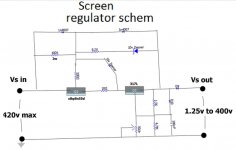
the irf540 mosfet follower is as simple as it is effective...
15v zener to protect gate-source terminals...
the resistor feeding the gates can be made high enough and
split in two with a ecap in the middle so that a slow ramping
up of voltage is possible....RC time constant / voltage calcultor
then zeners at the gate for voltage reference makes it regulated...
very simple and very capable...
I wouldn't use a Maida regulator for screen regulation, I've found this to be a pretty fragile design at high voltages.
Something based on the LR8N3 buffered by a mosfet follower would work well and can withstand considerably higher voltages than encountered here.
LR8N3-G Microchip Technology | Integrated Circuits (ICs) | DigiKey
IRF840PBF Vishay Siliconix | Discrete Semiconductor Products | DigiKey
I still think the gas tubes would be more fun personally.
I still think the gas tubes would be more fun personally.
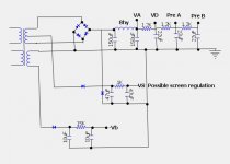
crazy that i am, i used both in my amp, the gas regulator also powers the lower voltage input stage, while serving as reference to mosfet followers....
Blencoe desccribes it as quite robust,at the max voltage of 400v there is only 6.8v across the lm317L. That being said I will likely just use a divider as this design uses.
yes, the input voltage - output voltage differential is one to watch...
and the average dissipation of the device must be considered when deciding to use heatsinks on them..
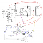
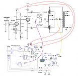
this is a nice template for screen regulator: p. milette designed this
DCPP Amp
http://www.pmillett.com/images/DCPP.h4.gif
Cool thanks for posting that Tony. That was an interesting amp! I have a lot of "spare parts" kicking around here. I was thinking I'd beef up the power supply. I have 2 47uf 630v , 2 22uf 630v 4 15uf 630v solen fast caps. I thought id convert over to a choke also I have a 157m Hammond 8h Choke I used fast caps once before in a power supply and the amp sounded good. I thought I'd try and use some. Is it a waste to use them for the reservoir cap do you think?
Here is the a schematic of the Altec 345 I may want to use in this amp. Maybe you guys would have a look and suggest any changes or tweaks you might try? I would change the bias circuit as per my other drawing in the previous schematic I posted.
Attachments
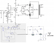
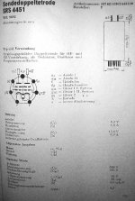
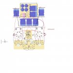
here is the schematic. Pasted on the variable screen regulator for fun. Dont know if I'd bother with it. Was looking at these tubes but not sure if the cage will fit, they seem kinda tall. SRS4453 – 829B - GU29 – 2x RFT Rohren-Tubes-Valves NOS/NIB | eBay
Attachments
Last edited:
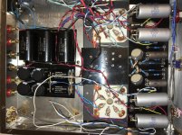
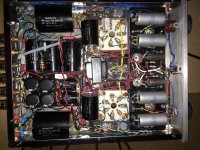
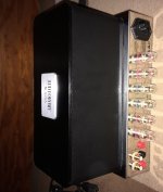
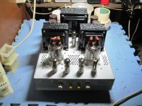
Here are a few pics of my progress. I also included my layout but its not complete. I still need to fit 4 more Solin PS caps in there (screen and input filtering) I put the Plate filtering the PI filtering and bias supply in roughly the same footprint as the old PS board. That is different than what the layout shows. I will also use 22uf Caps for the 6au7 and the Screen supply caps are 400v so they will be a little smaller. I also will try the variable regulated screen too. I'm waiting on a few parts for it. Its going to be tight build, but it should work!
Attachments
Last edited:
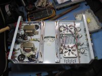
Progressing slowly but here is where I'm at if anyone is interested. I did not run the 6c4 and 6au6 with dc instead I wired them in series and used the elevated divider (that is not yet installed) I noticed the heater voltage was 14.2 volts so I put two .1ohm resistors in series with each leg. I checked the voltage again and its now 13.4 with all the tubes in,so I may try to get it down a little more. I dont have any 5watt in those very small values at the moment. I also have decided to remove the relay and go with only one input. I'm going to use a preamp with this amp anyway. I will post more as I complete. Happy Easter All!
Attachments
I was thinking it might be cool to triode connect the 6AU6. the plate voltage should not exceed 100v says the tube data.So close to +90V +/- 10% would be best. I guess I would need to adjust plate and cathode resistor to manage this. At about +90V and about 3mA, the bias would be around 1,8 V according to the 6AU6 datasheets. 1,8V/3mA = 600R. A 620 Ohms ½ Watt resistor will do no?. 250V – 90V = 160V / 3mA = 53,3k Ohms. A plate resistor of 47k or 56k 1 Watt should do I suppose. So this modification should increase the gain.
The input impedance of the 6C4 splitload phasesplitter seems high in the direct coupled mode, might there be a benefit possible in removing the cathode decoupling capacitor? Seems this design being as old as it is the high gain isn’t necessary with modern signal sources? The non decoupled cathode should provide some local FB and maybe linearise the input stage? This should be a benefit if this is in pentode or triode mode. Seems like maybe less noise and distortion of this stage. Any opinions?
The input impedance of the 6C4 splitload phasesplitter seems high in the direct coupled mode, might there be a benefit possible in removing the cathode decoupling capacitor? Seems this design being as old as it is the high gain isn’t necessary with modern signal sources? The non decoupled cathode should provide some local FB and maybe linearise the input stage? This should be a benefit if this is in pentode or triode mode. Seems like maybe less noise and distortion of this stage. Any opinions?
Attachments
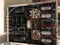
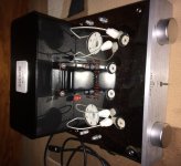
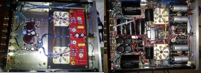
Went ahead a finished wiring her up. I'll put it on the DUT tomorrow and will do a once over later tonight. Hopefully all goes well. ") I put adjustable screen regulation in and bias pots for each plate. I put the test bias test points in where DVD used to be and drilled one extra hole. Hopefully the bias adjustment works out well. The Screen adjustment and test point is on the deck on either side of the new power supply choke. The smaller screen supply choke is directly underneath. Thanks to Tony and Kevin for their input!
I put adjustable screen regulation in and bias pots for each plate. I put the test bias test points in where DVD used to be and drilled one extra hole. Hopefully the bias adjustment works out well. The Screen adjustment and test point is on the deck on either side of the new power supply choke. The smaller screen supply choke is directly underneath. Thanks to Tony and Kevin for their input!
I put adjustable screen regulation in and bias pots for each plate. I put the test bias test points in where DVD used to be and drilled one extra hole. Hopefully the bias adjustment works out well. The Screen adjustment and test point is on the deck on either side of the new power supply choke. The smaller screen supply choke is directly underneath. Thanks to Tony and Kevin for their input!Attachments
Last edited:
- Status
- This old topic is closed. If you want to reopen this topic, contact a moderator using the "Report Post" button.
- Home
- Amplifiers
- Tubes / Valves
- Audioromy FU29 improvement and upgrades?