I have a AP1800D car amp with a completely blown psu section (all the power transistors are blown and a few smd components on the power side.) I dont really have an interest in fixing this amp for car use as the board is pretty burnt, although i could use a good class d home amp and i have a few transformers laying around from hometheater receivers. Before ive made a pioneer car amp work with a transformer by just applying the correct voltages to the voltage rails. Although on this amp when i applied +-70 volts to the rails, it did not turn on. I assume i need to apply power else where for the op amps and other components to turn on. Where else do i need to supply power to turn on this amp. Thanks for any help, these forums are the best.
Surely someone knows what voltages must be present where for the amp to function. Thanks for any help!
Are you even sure that it would be okay with 70V? And I hope you fed it DC unless you put the 70VAC before the amps rectifiers (if it works that way)
You could probably get an idea of the upper limit of voltages by looking at what voltage the filter caps of the amps power supply are rated at, however that doesn't mean that if they use 70V caps the supply might only be 50V. I just say this to make sure you aren't applying 70V to 50V caps or anything else obviously wrong like that.
You mentioned op-amps. Are you sure this amplifier actually has op-amps? If so than I'll tell you that op-amps will normally have both a positive and negative supply, commonly + and - 15VDC or similar. The other option is if they used a voltage divider to trick the op-amp into thinking its positive and negative supply (which I don't think a good amplifier manufacturer would do).
It all depends on what you know about electronics. Do all of this at your own risk and only follow my advice at your own risk, at your own discretion, and if you are competent to do so.
Assuming you can later properly remount the board with new thermal interface material on all of the active components, you might want to consider removing the whole amplifier pcb from the chassis, then follow the traces on the pcb. The other option would be to hunt around online for a possibly non-existent schematic of this particular amp.
As I said please only do this if you can do so safely and properly.
EDIT: And you must also consider the fact that if something was so catastrophic as to ruin the entire power supply of the amp, that the actual amplifier section might also be fried. I'm not sure why your exact amp died but it could be that the amplifier section had an issue (blown mosfet perhaps) and then overloaded and took out the power supply section.
Last edited:
Thanks for the suggestions, i have started trying to figure out some of the traces. I know how to keep safe (during testing, ive only applied +-20v to prevent a nasty shock), so far ive found 3 5v regulators that arent receiving power, and the two power torroids have some smaller secondary windings that i assume supply power to these regulators. One of them is grounded on the negitive B- and the other two are grounded on the regular ground plane. Any ideas on how i can supply them power? Im guessing i can supply about 7v to the ones that are grounded on the regular gound. but what about the one grounded to the negative B-? Thanks!!
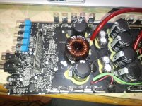
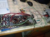
Here are a few pics of the regulators if that helps.
Edit: im pretty sure the amp was conected with reverse polarity and no fuse.
Edit: im pretty sure the amp was conected with reverse polarity and no fuse.
Attachments
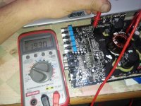
Thanks for the suggestions, i have started trying to figure out some of the traces. I know how to keep safe (during testing, ive only applied +-20v to prevent a nasty shock), so far ive found 3 5v regulators that arent receiving power, and the two power torroids have some smaller secondary windings that i assume supply power to these regulators. One of them is grounded on the negitive B- and the other two are grounded on the regular ground plane. Any ideas on how i can supply them power? Im guessing i can supply about 7v to the ones that are grounded on the regular gound. but what about the one grounded to the negative B-? Thanks!!
I understood most of what you said but I didn't quite catch the part about the 3rd regulator.
So lets see here, you have 3x 5V regulators that aren't getting power.
2x of the regulators have their grounds tied to the ground plane, the other regulator has its ground tied to what exactly?
EDIT: and are those three wires near the caps your inputs for your power? Exactly what voltages and at what current are you applying? Are you applying both a positive and a negative, if so, in what exact configuration. At first glance (and I might be completely wrong) it looks like there should be ground going to the middle, then your positive and negative supplies connecting to the other two wires whichever way seems appropriate. (I can't completely tell from the pictures)
Last edited:
The last regulator is grounded to the negative side of the high voltage supply. I applied +-20v in the pics, and that regulator had -20 at its ground. Thanks! I think once i can power them up it should work provided nothing else is blown, those regulators seem to supply power to the input sections
The last regulator is grounded to the negative side of the high voltage supply. I applied +-20v in the pics, and that regulator had -20 at its ground. Thanks! I think once i can power them up it should work provided nothing else is blown, those regulators seem to supply power to the input sections
EDIT: It looks like your one step ahead of me! I didn't see your last post until just now. Look like you did exactly what I was going to suggest below and it appears to be working.
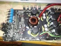
Judging from the pictures it looks to me (and once again I might be completely wrong, do this at your own risk) that the two filter caps next to the toroid pictured are wired like this +-+- so that the + of the cap in the bottom of the picture is positive, the - of the bottom cap and the + of the top cap in the picture should be tied together and at ground, and then the - of the top cap should be the negative supply.
So, judging from the picture, If I had 2 isolated 20VDC supplies, I'd connect them in such a way that they match perfectly with the cap, positives to positives, negatives to negatives. Like I said though this is an assumption based on the pictures, I might be wrong.
EDIT: It looks like your one step ahead of me! I didn't see your last post until just now. Look like you did exactly what I was going to suggest below and it appears to be working.
Judging from the pictures it looks to me (and once again I might be completely wrong, do this at your own risk) that the two filter caps next to the toroid pictured are wired like this +-+- so that the + of the cap in the bottom of the picture is positive, the - of the bottom cap and the + of the top cap in the picture should be tied together and at ground, and then the - of the top cap should be the negative supply.
So, judging from the picture, If I had 2 isolated 20VDC supplies, I'd connect them in such a way that they match perfectly with the cap, positives to positives, negatives to negatives. Like I said though this is an assumption based on the pictures, I might be wrong.
Yup, thats what ive done, but that only supplies power to the main output transistors, the op amps and other stuff seems to have its own separate supply.
Yup, thats what ive done, but that only supplies power to the main output transistors, the op amps and other stuff seems to have its own separate supply.
So as the amp is hooked up right now, those 5V regulators aren't doing anything (no output)?
Also, are you the one who took this apart (do you know how it looked before?)? It looks to me like many of the output transistors have been removed.
I'm surprised the op-amps aren't powered up because you'd think they would be by the logic that controls the power and protect lights, which seem to be working fine.
Last edited:
Yup,all terminals of the regulators are at their ground reference. I bought 3 blown amps from a guy with a backyard shop, i fixed two of them and im using them, this last one i was gonna toss it, but id rather put it to some use if its possible. my soldering iron is warming up, im gonna try and apply some power to the ones that are on the ground plane and see if anything changes.So as the amp is hooked up right now, those 5V regulators aren't doing anything (no output)?
Also, are you the one who took this apart (do you know how it looked before?)? It looks to me like many of the output transistors have been removed.
Yup,all terminals of the regulators are at their ground reference. I bought 3 blown amps from a guy with a backyard shop, i fixed two of them and im using them, this last one i was gonna toss it, but id rather put it to some use if its possible. my soldering iron is warming up, im gonna try and apply some power to the ones that are on the ground plane and see if anything changes.
I hope I can help you figure this out
")
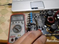
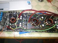
I think I may have found something of use. If you look at the picture attached to this post, I've put 3 red boxes around some diodes which look like they may be the rectifiers for the little separate supplies for those regulators, especially the 2 diodes in the middle box which look like they are arranged in a half wave rectifier.
You can see where they go better than me so let me know what you think.
Attachments
I hope I can help you figure this out
I think I may have found something of use. If you look at the picture attached to this post, I've put 3 red boxes around some diodes which look like they may be the rectifiers for the little separate supplies for those regulators, especially the 2 diodes in the middle box which look like they are arranged in a half wave rectifier.
You can see where they go better than me so let me know what you think.
Yes, all the diodes with the stripe facing the left go the the input of the regulator nearest to them. The also all have a cap connected to them, so they are rectifiers. The one with the stripe facing the left seems to also have a cap, but i believe it is connected to the daughter board. Also the ground of the regulator closest to the bottom of the picture is actually connected to the output of the transistors, where speaker output torroid is connected
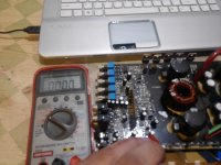
I also disconnected the smaller windings on the torroids and used my multimeter on the beep setting to see to which terminals the diodes were connected
I have no idea why they would be connected to those toroids.
If you are sure that those 3 devices are regulators, then you should be able to find their rated input voltages, and feed those voltages to them.
Last edited:
Thats what i did, i applied 12v to the inputs of the lower two regulators and they started putting out 5v just fine, (they pulled about 100ma so i dont think anything should fry) and while connecting them, i heard a slight pop from the speaker, but that may be because one of them is grounded on the speaker output. hmm, we are getting close! ThanksI have no idea why they would be connected to those toroids.
If you are sure that those 3 devices are regulators, then you should be able to find their rated input voltages, and feed those voltages to them.
Thats what i did, i applied 12v to the inputs of the lower two regulators and they started putting out 5v just fine, (they pulled about 100ma so i dont think anything should fry) and while connecting them, i heard a slight pop from the speaker, but that may be because one of them is grounded on the speaker output. hmm, we are getting close! Thanks
Is that one grounded on the positive or negative of the speaker output?
Its the middle one and the lower most one (which is gounded on the speaker output.)Is that one grounded on the positive or negative of the speaker output?
- Status
- This old topic is closed. If you want to reopen this topic, contact a moderator using the "Report Post" button.
- Home
- General Interest
- Car Audio
- Audiopipe AP1800D to 120v conversion help