Yes! RF matters, and some equipment ignores it. Second the thoughts on shielding and such- if you live in the city, the RF environment is terrible. May not be better in the country. All rectifier bridges should have bypassing and/or have diodes chosen for low RF "splashing", or whatever they call it. A properly designed power supply in a properly shielded enclosure shouldn't need or care if it has an external line conditioner or not, and it should make no difference to the sound. A poorly designed power supply, OTOH...
As for cables, I've heard differences at times. Consider that given the input impedance of a (my) power amp, and a typical amount of cable capacitance, there can be as much as 25 degrees of phase shift between input voltage and current at 10kHz. I'm not sure how serious this is, but it's large enough to spend some time considering.
As for cables, I've heard differences at times. Consider that given the input impedance of a (my) power amp, and a typical amount of cable capacitance, there can be as much as 25 degrees of phase shift between input voltage and current at 10kHz. I'm not sure how serious this is, but it's large enough to spend some time considering.
Conrad Hoffman said:A properly designed power supply in a properly shielded enclosure shouldn't need or care if it has an external line conditioner or not, and it should make no difference to the sound.
There's the rub. The domestic environment is full of RF from wireless devices well into the GHz range. Anyone who's spent time modelling supplies in Spice using component models with approximations for parasitics knows how incredibly difficult it is to filter that crud with common audio components. The interwinding capacitances of the typical 10H PS inductor pass RF easily. A straight C supply is hopeless (and bypassing doesn't really work.) So far the only solid way Spice results have shown significant attenuation at high RF is by using small value LC stages of uH and nF, pure audiophoolery.
I don't know why anyone would use "common audio components" on an RF problem. I'd expect them to use the RF techniques that are many decades old. IMO, it's not all that difficult, it's just that many audio people haven't paid any attention to the issue. There's certainly plenty of info out there- a free subscription to Conformity magazine is an excellent place to start. Growing up, my dad was a ham, so maybe I'm sensitized to RF issues.
Re: Edjakashun...
Hey, that's my line...
If you assume all the current within the litz is going in the same direction, then the litz insulation interstrand plays no role in the dieleictric.
To paraphrase Neo..."there is no fence".
We cannot hear frequencies that have skin depths in the microinch realm.
Think of the extreme cases. Full conduction allows the conductor toroidal eddy currents which is the basis for skin effect current redistribution, and broken interstrand conduction would approach litz operation...the difference between the two extremes is 15 nH per foot out of about 200 nH per foot.... And the interstrand potentials resulting from oxidation within the wire is what, nanovolts? Given the difficulty of measuring these low levels at the frequencies of interest (I do not know how to embed tap wires within the stranded structure without disturbing the current flow pattern, nor how to prevent field intercept errors in the taps), it is quite sexy for the vendors to cite this phenom as a possibility without worrying about somebody proving it erroneous via test.
Cheers, John
EC8010 said:When I were a lad (dinosaurs still roamed the earth)
Hey, that's my line...
Well, kinda sorta. The lumped element assumption used for audio frequencies is a derivation of the transmission line equations. Use of prop velocity for short length wires at audio is of course, silly. But, remember that the prop veocity is related to the effective dielectric constant of the cable (mu times epsilon), hence it's storage of energy (L and C). Also , LC = 1034 DC is derived from transmission line analysis.. (this relation states that the LC product can be no less than 1034 times the DC of a coax, L in nH, C in pF.)EC8010 said:To get back on topic, I know enough to know that the most commonly touted "scientific" explanations for audio cable sound (skin effect, transmission line) are hocus-pocus at best. Skin effect and transmission lines apply at RF, not audio.
BudP said:Really, I was just inquiring if the notable effect of E Field / D Field activity, at a static moment, where field vectors change and then flow as B Field to the next vector change, within a conductor containment, might be more noticeable, from a measurement perspective, in Litz wire, than that same activity with a solid conductor.Bud
If you assume all the current within the litz is going in the same direction, then the litz insulation interstrand plays no role in the dieleictric.
MJL21193 said:
John, I had you pegged wrong, thought you were one of the "others"
To paraphrase Neo..."there is no fence".
mach1 said:Given that copper and silver are both prone to surface oxidation, and that silver oxide is a much better conductor than copper oxide, might it then be plausible that they sound different at high frequencies?
We cannot hear frequencies that have skin depths in the microinch realm.
mach1 said:Also, at the interface between strands which display an oxide coating, is it possible that inter-strand signal transfer becomes non-linear (it has been suggested that the junction may display qualities similar to a diode). If so, is it possible that the degree of non-linearity may vary between copper and silver?
Think of the extreme cases. Full conduction allows the conductor toroidal eddy currents which is the basis for skin effect current redistribution, and broken interstrand conduction would approach litz operation...the difference between the two extremes is 15 nH per foot out of about 200 nH per foot.... And the interstrand potentials resulting from oxidation within the wire is what, nanovolts? Given the difficulty of measuring these low levels at the frequencies of interest (I do not know how to embed tap wires within the stranded structure without disturbing the current flow pattern, nor how to prevent field intercept errors in the taps), it is quite sexy for the vendors to cite this phenom as a possibility without worrying about somebody proving it erroneous via test.
Cheers, John
MJL21193 said:I was refering to a post in the biwiring thread, that was quasi "others" sounding.
I understood your reference, guess he didn't tie the two..
You are indeed correct, what I stated absolutely looks like some garbage explanation heaped upon the consumer by some vendor.
But really, it's the other way around...the typical vendor claptrap is written to look like a scientific explanation.. So when a scientific one comes along that is not fully understood, it is rather easy to lump it into the snake oil category.
My analysis of bi vs monowiring is based on simple math in a way not normally considered. Working in a different field give me an advantage in that I don't normally look at problems the way most do...Nature of the beast (work, not me)..
Cheers, John
jneutron: You wouldn't care to post a link to your biwiring maths would you?
Thinking back to audio transmission lines, I did once measure a five mile length of twisted pair and it genuinely came out at near enough 600 Ohms. Another deliberate transmission line used by the Post Office (who handled telecommunications at that time) was loaded plant, whereby the cable had inductors added every fifty yards or so. It gave a better HF response at the expense of a precipitous roll-off and phase behaviour that was completely unmatchable to unloaded plant for stereo.
Thinking back to audio transmission lines, I did once measure a five mile length of twisted pair and it genuinely came out at near enough 600 Ohms. Another deliberate transmission line used by the Post Office (who handled telecommunications at that time) was loaded plant, whereby the cable had inductors added every fifty yards or so. It gave a better HF response at the expense of a precipitous roll-off and phase behaviour that was completely unmatchable to unloaded plant for stereo.
Re: Re: Edjakashun...
John
"If you assume all the current within the litz is going in the same direction, then the litz insulation inter strand plays no role in the dielectric."
Excellent. So, may I then assume that any exterior dielectric material will have an effect upon all insulated strands? One that is altered only by their distance from the dielectric, for the length they are actually under that dielectric?
Having already assumed this as true, of course, what do you think would be the effect of placing a dielectric tube on, at the the middle of a meter of Litz? Say a constant of 4 or so and an inch of this in the middle of a meter length of cable, with the rest of the cable encased in sized but undyed 100% cotton, with more of the same dielectric constant at either end and also about 1 inch long?
Can you make an educated surmise about E Field retention, as a field of organized coherent data? One with low "amplitude" electrons, and their ability to adhere to dipole electrons, or perhaps, a sheet of lower threshold electrons, that are already adhered to the dipole electrons of the 1 inch dielectric material encasement?
Bud
EC8010 said:
No, I don't have one of those. $1200? It's a steal. Nice metalwork.
No, no. It's not $1200. Look back to my post #149 where I first mentioned it. It's $7881.81!
This is all such BS
Sorry guys, but damn near all of you here have been duped, and are "audiophooles"
I'm a lifelong musician, have spent much time in recording studios, been to audio engineering school, etc., and I have to tell you this entire "audiophile" industry is basically a load of crap.
I've read lots of the magazines, websites, etc., and i have to tell you, NOT ONE OF THESE PRODUCTS advertised or talked about can be found in professional recording studios.
This is where all the music you guys are listening to originates: this gear HAS to ACTUALLY PERFORM to standards as perfect as possible, no voodoo tolerated.
If you're going to argue with me, sorry - it ain't gonna hold water - because ALL of your statements assume that the source material (music recorded) is absolutely perfectly and flawlessly recorded.
And NONE of the brand names I've ever heard reference to in either the magazines or blogs, or forums is seen is professional grade recording studios.
And by the way, either are any of these absurd multi thousands of dollar cables either - XLR sheilded balanced is as good as it gets.
Here's an equipment list of the gear in Peter Gabriels' - New World Studios:
http://www.realworld.co.uk/
(This isn't his personal studio, it's a world class studio used by many musicians from all over the world.)
This entire market is created for you turbo-home enthusiasts, which is fine, but to think that having some audiophile magazine (or anyone not associated with the actual recording industry) is some sort of "stamp of approval" is just ridiculous.
And as far as AC power cords go; you're paying hundreds (or even thousands) of dollars for "exotic" "high-end" AC cords, then plugging them into your house wiring which uses standard grade Romex wire.
Hello? McFly? Do you guys think AC power spontaneously generates at the wall socket?
It just blows my mind listening to you guys.
If you REALLY want the best, then start strafing the internet for true professional recording studio websites. They all list their gear.
Buy that stuff. It's THE best stuff there is.
Matt
Well gosh, matt1, here we are, a bunch of engineers and we've got it all wrong. It's just as well you're here to set the record straight and tell us how wrong we all are. Just one thing, though, how come you didn't notice that we're all just as sceptical, so we're discussing the physics of all the claims?
It's because matt1 is wrong. Companies like this market to whom?
http://www.zaolla.com/zaolla_guitar_instrument.html
No studios use 'audiophile' and tweak components? Just last week I bought a Telarc Cyrus Chestnut release and the liner notes mentioned all the cables used were MIT. See links below, searched almost at random.
http://gcaudio.com/products/reviews/infoshunyata.html
http://www.monstercable.com/FrangioniFiles/default_v01.asp
The client list of Chord Electronics, one of Britian's premier high end audiophile companies:
http://www.chordelectronics.co.uk/clients.asp
Chord doesn't show it, but Real World Studios also use Chord. These are results of a lazy, half-hearted couple minutes of search.
Since matt1 knows what's the best there is I assume he is not very technically educated.
Only salespersons know "the best" equipment while engineers usually don't - because they know the technical reasons behind the tradeoffs in equipment.
And there exists nothing in this world without tradeoffs.
Regards
Charles
Only salespersons know "the best" equipment while engineers usually don't - because they know the technical reasons behind the tradeoffs in equipment.
And there exists nothing in this world without tradeoffs.
Regards
Charles
biwire math
1. Kirchhoffs law: the sum of current at a node is zero. In other words, what goes in, goes out.
2. resistive dissipation: The power lost in a resistor is P = I2R
3. Algebra: (A + B)2 = A2 + B2 + 2AB
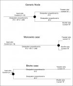
I attach a depiction of the wires for discussion. The top diagram is the generic node diagram, the amp is to the left, the speaker is to the right. This node represents where the currents of the woof and tweet part ways. The crossover components are off the page to the right, and for the purposes of this exercise, the values of the crossover are unimportant.
Now, put a current "A" into the wire on the left, this current is 1 ampere at say, 10Khz. Put a current "B" into the wire, it being 1 ampere at 20 hz. On the right side, the crossover figures out where these signals go, so to the right of the node, each current travels a specific wire.
The current within the wire on the left of the node is A + B. The dissipation in that wire, from the equation, is P = I2R, with I = (A + B), so :
Pleft = (A2 + B2 + 2AB)R
The current within the upper right wire (tweet)is A, it's dissipation is:
Ptweet = A2 R
The current within the lower right wire is B, it's dissipation is:
Pwoof = B2 R.
Now, diagram two shows the node slid to the right. This represents monowiring. Now, what is the bulk of the powerloss within the wire: Pmonowire = (A2 + B2 + 2AB)R
Diagram 3 is the node slid to the left..now what is the powerloss within the wires:The sum of the losses of the upper and lower wires..
Or, Pbiwire = Ptweet + Pwoof
Pbiwire = A2 R + B2 R, or (A2 + B2) R
Contrast this with Pmonowire = (A2 + B2 + 2AB)R
Subtracting Pbiwire from Pmonowire gives:
Pdiff = 2AB times R.
Cheers, John
EC8010 said:jneutron: You wouldn't care to post a link to your biwiring maths would you?
1. Kirchhoffs law: the sum of current at a node is zero. In other words, what goes in, goes out.
2. resistive dissipation: The power lost in a resistor is P = I2R
3. Algebra: (A + B)2 = A2 + B2 + 2AB
I attach a depiction of the wires for discussion. The top diagram is the generic node diagram, the amp is to the left, the speaker is to the right. This node represents where the currents of the woof and tweet part ways. The crossover components are off the page to the right, and for the purposes of this exercise, the values of the crossover are unimportant.
Now, put a current "A" into the wire on the left, this current is 1 ampere at say, 10Khz. Put a current "B" into the wire, it being 1 ampere at 20 hz. On the right side, the crossover figures out where these signals go, so to the right of the node, each current travels a specific wire.
The current within the wire on the left of the node is A + B. The dissipation in that wire, from the equation, is P = I2R, with I = (A + B), so :
Pleft = (A2 + B2 + 2AB)R
The current within the upper right wire (tweet)is A, it's dissipation is:
Ptweet = A2 R
The current within the lower right wire is B, it's dissipation is:
Pwoof = B2 R.
Now, diagram two shows the node slid to the right. This represents monowiring. Now, what is the bulk of the powerloss within the wire: Pmonowire = (A2 + B2 + 2AB)R
Diagram 3 is the node slid to the left..now what is the powerloss within the wires:The sum of the losses of the upper and lower wires..
Or, Pbiwire = Ptweet + Pwoof
Pbiwire = A2 R + B2 R, or (A2 + B2) R
Contrast this with Pmonowire = (A2 + B2 + 2AB)R
Subtracting Pbiwire from Pmonowire gives:
Pdiff = 2AB times R.
Cheers, John
Attachments
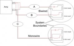
Now, lets examine a specific setup, that being one amp with both moniwiring and biwiring attached to the same output.
I've established system boundaries around the speakers. The only energy input into those boundaries is the wires.
With only one amplifier, both speakers are seeing the exact same terminal voltage at the amp end, that removes amplifier "reactions" as the source of any difference.
From the previous post, it is clear that the powerloss between the amplifier and both speakers is different, the C, or monowire case, having that 2AB loss component that the upper biwire set doesn't have.
The assumption that biwiring makes NO DIFFERENCE, means that even though the lower speaker DOES NOT SEE THE SAME POWER INPUT because the losses in the feedwires are different, the speaker still gets the same power?
The assumption that biwiring makes no difference violates the first law of thermodynamics.
Cheers, John
Attachments
phase_accurate said:If you add two non-correlated currents their sum isn't
A+B
but
SQRT(A^2 + B^2)
Now repeat your calculations please
Regards
Charles
Now THAT would be the error I've been unable to find...
However, consider a point in time where A = 1/2, and B = 1/2.
A squared is 1/4, B squared is 1/4, the sum of that is 1/2.
The square root of 1/2 is .7071, but yet Kirchhoffs law states that the current on the left at all instants in time, is equal to the sum of the two on the right, that sum would be 1.
Now consider A = 1, and B = -1.
A squared is 1, B squared is 1, adds to 2...square root is 1.414.
But the currents are equal and opposite, so net current is zero..in accordance with Kirchoffs law.
I believe you're thinking of rms power...not current.
Cheers, John
ps..edited for clarity.
Re: Re: Re: Edjakashun...
No. Wires that are hidden by others will not be seen by the dielectric. Consider a 6 around 1 cable. External voltage fields will not be affected by the voltage of the inner wire, regardless of that wire's potential. So the composite dielectric will be the wire insulation presented to the external dielectric added to the external dielectric.
There will be a slight increase in the capacitance of the system. The change depends on how far away the return wire is.
One can certainly call an e-field coherent, as well as the dielectric's response to the e-field. But as far as the signal is concerned, it's just energy storage via capacitance as well as losses due to the dielectric. It is not concerned with what the signal actually is, but the instantaneous value added to historical charging of the dielectric.
"Amplitude of the electrons", "dipole electrons", and "lower threshold electrons" are terms which I have never heard before so do not know what you are talking about.
"Adhering electrons" implies the accumulation of charge..this is not what happens within a cable which passes AC signals.
It must be noted however, that a single wire with insulation will have a potential voltage on the insulation surface, this voltage a result of the capacitive divider between the insulation and the air capacitor to the other wire or chassis. When you touch the wire, you typically provide 1000 pf to the system as you approach, so the capacitive divider shifts the surface voltage towards your voltage..leaving the voltage potential to the insulation thickness.
This is why HV wires attract dust, this is why an inadequately insulated wire in space looks fine, but when you go to touch it, you get zapped..fun stuff.
Cheers, John
BudP said:Excellent. So, may I then assume that any exterior dielectric material will have an effect upon all insulated strands?
No. Wires that are hidden by others will not be seen by the dielectric. Consider a 6 around 1 cable. External voltage fields will not be affected by the voltage of the inner wire, regardless of that wire's potential. So the composite dielectric will be the wire insulation presented to the external dielectric added to the external dielectric.
BudP said:.... what do you think would be the effect of placing a dielectric tube on, at the the middle of a meter of Litz? Say a constant of 4 or so and an inch of this in the middle of a meter length of cable, with the rest of the cable encased in sized but undyed 100% cotton, with more of the same dielectric constant at either end and also about 1 inch long?
There will be a slight increase in the capacitance of the system. The change depends on how far away the return wire is.
BudP said:.... Can you make an educated surmise about E Field retention, as a field of organized coherent data? One with low "amplitude" electrons, and their ability to adhere to dipole electrons, or perhaps, a sheet of lower threshold electrons, that are already adhered to the dipole electrons of the 1 inch dielectric material encasement?
One can certainly call an e-field coherent, as well as the dielectric's response to the e-field. But as far as the signal is concerned, it's just energy storage via capacitance as well as losses due to the dielectric. It is not concerned with what the signal actually is, but the instantaneous value added to historical charging of the dielectric.
"Amplitude of the electrons", "dipole electrons", and "lower threshold electrons" are terms which I have never heard before so do not know what you are talking about.
"Adhering electrons" implies the accumulation of charge..this is not what happens within a cable which passes AC signals.
It must be noted however, that a single wire with insulation will have a potential voltage on the insulation surface, this voltage a result of the capacitive divider between the insulation and the air capacitor to the other wire or chassis. When you touch the wire, you typically provide 1000 pf to the system as you approach, so the capacitive divider shifts the surface voltage towards your voltage..leaving the voltage potential to the insulation thickness.
This is why HV wires attract dust, this is why an inadequately insulated wire in space looks fine, but when you go to touch it, you get zapped..fun stuff.
Cheers, John
SY said:Unless there's a very strange test signal involved, I'd expect the currents to be correlated anyway.
Well, there again, you're talking music...who are you to inject a discussion of "music" into a discussion of speaker wires??HMM??
I limit my discussion to two sine waves far enough apart that they divert cleanly at the crossover. Non correlation is simply choosing two signals which are not frequency multiples.
Cheers, John
- Status
- This old topic is closed. If you want to reopen this topic, contact a moderator using the "Report Post" button.
- Home
- General Interest
- Everything Else
- "audiophools"