Even if you take away the resistor and feed the LTP collector directly and only to the base of a VAS transistor the current flow into the base develops a voltage across the internal resistance of the transistor. It is still voltage controlled. The internal resistance is not very linear and this would degrade the performance of the amplifier.
The physics of a bipolar transistor are such that the current flow from collector to emitter is a function of the control voltage - not the input current. The current is a consequence of finite input impedance. It is the distribution of charge in the base region that controls the device. Because bipolar devices have such low input impedance it is important to consider the current that must be supplied and this leads to the viewpoint of current control.
If you always provide enough (even unlimited) current drive to a bipolar device so that it`s never starved then only the base-emitter voltage is important for control.
When you look at the physics, all active devices are voltage to current converters. Only the introduction of load impedances to make a circuit allows us to create a TIS.
Ok, I could launch into a long explanation about why, with a Cdom cap (or MIC cap) it's still a TIS but I'll spare myself and everyone else here the agony of another protracted exchange leading nowhere. Instead, I point you to Bruno Putzey's 'The F-word . . .' article and leave it at that.
Peace.
Member
Joined 2009
Paid Member

Peace indeed - we will agree to disagree
.
Me too. The base current is from recombination in the base BTW. Make it super thin (super-beta) and it can be very low. Base current is completely incidental to the operation of the device, i.e. the Ic vs. Vbe relationship is the fundamental one.
Make it super thin (super-beta) and it can be very low.
Yah, but then ya gotta make sure Bvces doesn't dive below Bvcbo. I've toasted many a device during high slew operation because of punch through.
jn
Peace indeed - we will agree to disagree
p.s. no disagreement with Bruno's article - he doesn't show transistors, only circuit blocks. A circuit block can be a TIS since it can include the load impedances.
Precisely
No active devices are current controlled; they are all voltage controlled devices.
I don't think anybody disagrees with that.
Base current is completely incidental to the operation of the device, i.e. the Ic vs. Vbe relationship is the fundamental one.
True, but with shunt-shunt feedback courtesy of the Miller compensation capacitor, the second stage becomes a transimpedance amplifier, taking a current at its input and delivering a voltage at its output.
Careful reading of the following paper is called for:
http://ece.wpi.edu/~mcneill/524/handouts/solomon.pdf
Last edited:
I don't think anybody disagrees with that.
True, but with shunt-shunt feedback courtesy of the Miller compensation capacitor, the second stage becomes a transimpedance amplifier, taking a current at its input and delivering a voltage at its output.
Topological choice, what about shunt compensation to ground? Why use two stages when one is all you need.

Originally Posted by Bigun
with Bruno's article - he doesn't show transistors, only circuit blocks.
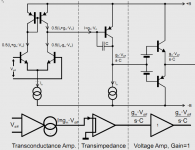
Actually he does show transistors, with dashed lines to indicate each stage !
Attachments
Member
Joined 2009
Paid Member
Only snag is it isn't a "VAS"; it is, in fact, a transimpedance stage (TIS).
It is in fact not always a transimpedance stage, and even in classical Miller-compensated designs where it acts that way over a large portion of the audio range, it is not always a transimpedance stage. It is usually NOT a transimedance stage in no NFB amplifiers.
Doug Self (if he was the one, I don't know) used a good choice with the term VAS. Insisting on using TIS for it only creates confusion. We don't need more of that.
Cheers,
Bob
Ha ha. Sneaky Scott.
Yes, the feedback makes it a TIS so it depends on one's definition of stage (before or after feedback is applied).Topological choice, what about shunt compensation to ground? Why use two stages when one is all you need.
I am not sure I comprehend; are you refering to your AD797?
As Scott Wurcer also agrees, it is a TIS due to the shunt-shunt negative feedback supplied by the Miller capacitor. It should never have been called a "VAS".It is in fact not always a transimpedance stage, and even in classical Miller-compensated designs where it acts that way over a large portion of the audio range, it is not always a transimpedance stage. It is usually NOT a transimedance stage in no NFB amplifiers.
Doug Self (if he was the one, I don't know) used a good choice with the term VAS. Insisting on using TIS for it only creates confusion. We don't need more of that.
Cheers,
Bob
Please read page 3 of Solomon where he says
http://ece.wpi.edu/~mcneill/524/handouts/solomon.pdfAn examination of (1) confirms the way in which the amplifier operates: the input pair and current mirror convert the input voltage to a current gmlvin. which drives the base of the second stage. Transistors Q5, Q6, and Q7 simply multiply this current by B^3 and supply it to the load RL.
Last edited:
- Status
- This old topic is closed. If you want to reopen this topic, contact a moderator using the "Report Post" button.
- Home
- Amplifiers
- Solid State
- Audio Power Amplifier Design book- Douglas Self wants your opinions