The voltage difference between VAS and output stage is negligible. It is unable to form another pole.
Here is what I am talking about at http://www.diyaudio.com/forums/soli...-self-wants-your-opinions-77.html#post3465453
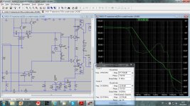
2 pole is there, but it is not because of TMC network.
I simulated TMC without miller capacitor connected. Here we got 2 pole.
What you need to simulate is the total loop gain enjoyed by the second stage and the output stage with "TMC". Try in in LTSpice; i doubt that it can be done accurately in Multisim.
Last edited:
What you need to simulate is the total loop gain enjoyed by the second stage and the output stage with "TMC". Try in in LTSpice; i doubt that it can be done accurately in Multisim.
Is this correct way to simulate TMC?
Damir
Attachments
Actually as was refering to the JL Hood design that has emitter degeneration for the LTP and then pervesely bypasses it with a large capacitor. Also mirror degeneration resistors are used and then bypassed by capacitors. The whole design is a mess.
I second that. In this case, the emperor (guru?) has no clothes, I am sorry to say. However, RIP JLH.
I've already done the simulation as indicated here:
http://www.diyaudio.com/forums/soli...-self-wants-your-opinions-73.html#post3463332
See below:
.....I am also a bit dubious about the utility of the 680 ohm (R13) in series with the MIC capacitor. The resistor adds a zero to the major loop gain response that is far beyond unity loop gain. The value of this resistor should have been in the region of 2.2K to bring the zero closer to unity loop gain frequency so as to enhance stability margins. Moreover if the zero is placed just before unity loop gain frequency, it has the effect of grossly extending the unity loop gain crossover, which may again compromise stability margins.
2.2k MIC resistor is about half the global feedback resistor so the gain margin for the global loop would be ~6dB. I guess this is OK since it's set by resistors rather than less-reliable components. Is this the best value, or just the limit of how far you were willing to push it?
Additionally, care must be exercised as inclusion of R13 in series with the MIC capacitor compromises the MIC local loop's stability margins.
Did you vary (increase) the MIC capacitor to keep the ULGF constant while increasing the MIC resistor? Was the compromise to the MIC loop's stability due to the lighter load on the VAS/TIS due to the increased MIC resistor?
poles
Hi jcx,
Probably you have overlooked above post, but I would like to get an answer from you, please.
Cheers,
E.
Hi JCX,
What about output stage inclusive compensation (a la Cherry). Is it single pole or two pole? Provided that the whole thing has been made stable, I'm inclined to call that also two pole compensation.
Cheers,
E.
Hi jcx,
Probably you have overlooked above post, but I would like to get an answer from you, please.
Cheers,
E.
Comments from other experts are also appreciated.
Maybe just comments from others?
Unless I misunderstand what you mean by the Cherry reference then it seems that simple Output Inclusive Compensation should be one-pole.
Why would it be two?
Best wishes
David
Last edited:
Did you vary (increase) the MIC capacitor to keep the ULGF constant while increasing the MIC resistor?
Never mind this part - I thought the resistor would start to affect the global ULGF at lower values than it actually does. The MIC resistor has to be almost equal to the feedback resistor before the effect is significant.
Was the compromise to the MIC loop's stability due to the lighter load on the VAS/TIS due to the increased MIC resistor?
Still interested in this part though. How does what follows match your results on Bob's amp?
For the discrete amp from post 751, I set Rmic to 6.8k (~one-third of the global feedback resistor). For 10MHZ ULGF of the MIC loop, it needed an 8pF Miller cap around the VAS/TIS. MIC loop phase margin was 68 degrees and gain margin was 14dB.
Without MIC resistor, 8pF Miller cap gave 18 degrees MIC loop phase margin (at 50MHz) & 3dB gain margin. A 22pF Miller cap was needed for 68 degree phase margin (at 22MHz); and 43pF Miller cap for 10MHz MIC ULGF (at 105 degrees margin).
When you say that you mean the system then the answer is "it depends".
Since OIC amplifiers are notorious for instability some presumably have more than two poles.
Even Miller compensated amps have second order behaviour, just not where we normally care.
Best wishes
David
Since OIC amplifiers are notorious for instability some presumably have more than two poles.
Even Miller compensated amps have second order behaviour, just not where we normally care.
Best wishes
David
MIC and improved noise
While we are on the topic of MIC an idea occurred to me.
Since MIC breaks the slew rate/Miller cap./LTP emitter resistor limitation then it would be possible to reduce the LTP emitter resistors and improve the noise without problems from reduced slew rate.
Obviously that would only make a practical difference if the feedback network and source were low impedance.
Has anyone else considered this?
It's for a tri-amp with very efficient compression drivers so yes, it does matter.
Best wishes
David
When you say that you mean the system then the answer is "it depends".
Since OIC amplifiers are notorious for instability some presumably have more than two poles.
Even Miller compensated amps have second order behaviour, just not where we normally care.
Best wishes
David
Hi David, now you are close to what I'm after.
While we are on the topic of MIC an idea occurred to me.
Since MIC breaks the slew rate/Miller cap./LTP emitter resistor limitation then it would be possible to reduce the LTP emitter resistors and improve the noise without problems from reduced slew rate.
Obviously that would only make a practical difference if the feedback network and source were low impedance.
Has anyone else considered this?
It's for a tri-amp with very efficient compression drivers so yes, it does matter.
Best wishes
David
Hi David,
Yes, we are thinking alike. I think I mentioned in another post somewhere earlier this week that one advantage of MIC was that it could allow less degeneration of the input stage. I don't think I explicitly mentioned that lower noise would be a resulting benefit, however.
Cheers,
Bob
Wat are OIC amps?Since OIC amplifiers are notorious for instability
I thought I was keeping up wid dem evil TLAs but I'm fast falling behind cos the rate of advancing polysyllabicity.
Then there's dem new (possibly pseudo) guru names like Middlebrook, Tian etc to go with the Holy Baxandall, Cherry, Cordell, Self et al
I'm not sure you gain much from this.I think I mentioned in another post somewhere earlier this week that one advantage of MIC was that it could allow less degeneration of the input stage.
In ANY feedback network, one of the most powerful tools available against instability is reducing the transconductance of the 'input stage'.
In the traditional 'Miller across the VAS', this is used to aid stability of the 'whole' amp.
In a pure Cherry (and also its evil TMC) version, his VAS emitter resistor aids the VAS + OPS loop.
In a QUAD type triple or a CFP, an emitter resistor on the first device can cure evil 'parasitics'.
Though each case has to be analysed individually, you will have reduced the need for less gm by compensating with your RC across the LTP collectors on your MIC. [deleted 2 pages of rant re why this isn't Miller bla bla]
One could argue that with a traditional 'Miller across the VAS' amp, you could get away with less degeneration by using RC across the collectors of the LTP ... or that you could get rid of the RC on your MIC by decreasing gm as it directly affects the MIC loop.
In all these case, the clever bit is ensuring the reduced gm doesn't reduce the feedback where you want it. This is the case if the input is mostly current driven so it's gm doesn't have first order influence on loop gain.
Did you vary (increase) the MIC capacitor to keep the ULGF constant while increasing the MIC resistor? Was the compromise to the MIC loop's stability due to the lighter load on the VAS/TIS due to the increased MIC resistor?
I kept the input inclusive Miller compensation capacitor constant. At this stage I am not certain why the resistor increases instability in the minor loop. I suspect it's due to the fact that the zero introduced by the resistor in the major loop appears as a pole in the minor loop.
- Status
- This old topic is closed. If you want to reopen this topic, contact a moderator using the "Report Post" button.
- Home
- Amplifiers
- Solid State
- Audio Power Amplifier Design book- Douglas Self wants your opinions