It is always interesting to see approaches to achieving low distortion with low quiescent bias currents in class AB designs, if that is what you are referring to. Particularly with MOSFETs, transconductance droop at lower bias currents can be a source of distortion. That was the main reason that I introduced Error Correction to vertical MOSFET power amplifiers.
Cheers,
Bob
Yes, true, error correction is useful to cancel crossover error that NFB could not reject it most in 5kHz and up, and normally laterals also still need around 250mA bias to get low crossover error.
Also what peavey, I also can't found it with google, I hope anyone could show them. I don't like that spiky crossover error too. I think many people agree we doesn't like that spikes.
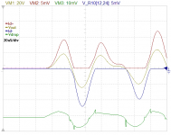
I am currently increasing my mosfet bias at HF operation, ofcourse not low bias anymore at high difficulty operation (waste power), but it has low bias normally 10-30mA at idle and normal operation. I still haven't other solution than this for long time.
I post old version here:
http://www.diyaudio.com/forums/ever...si-not-bad-really-i-post-some-proof-here.html
This picture help to show how it work, but I really sorry I am not sharing schematic for now. I can only share on how it work. Picture is showing output stage only without global NFB.
Attachments
No, I don't know that Proaudio factory is the same of Toshiba (fos example) factory.
So I have possibility to get one ACD101NDD? I have a final stage with 11 pair of mosfet, only one n-nos is short so I hope that I can substitute only this one, 11 pair of this mosfet is not cheap.
So I have possibility to get one ACD101NDD? I have a final stage with 11 pair of mosfet, only one n-nos is short so I hope that I can substitute only this one, 11 pair of this mosfet is not cheap.
Exicon
http://sound.westhost.com/project101.htmI
This link says a lot of good things
If you set the bias to 100 mA that was said to be the point at which FET's of the Hitachi type start to give their best . Personally I set them by ear and fingers ( how hot ) this agrees surprisingly well with oscilloscopes . This is the joy of FET's . This advice if class B .
Strictly speaking Szikai pairs are best for no global feedback amps . However they need setting by oscilloscope and very fancy biasing .
You will find FET's of this type will give surprising results at zero bias . That has to be a promising start . You will not match them as P and N are different . An amp I built recently at 0.7 A bias was 1.9 V and 1.4 V from center voltage
for N and P types . I find at 100 mA 1.2 V bias between gates is about what you will see . That amp sounded good with and without feedback . I also have a preference to have it without . You can if careful get very low distortion even if class B and no feedback . There is no exact bias point for FET's . However where they go from negative to positive temperature coefficients is about right ( 100 mA ) . I say Hitachi as most follow that pattern . BUZ , EXICON and HITACHI
I find 5.6 mA a good driver current and 220R stopper resistors . Increase driver current to have a sharper sound ( better square waves at 30 kHz ) . Even 2 mA will do to drive them . Real music does not have 100 watts at 20 kHz . If using less driver current and sound is good , then it's good . 8 mA is usually my limit .
FET's are static sensitive . Take precautions . Measure voltages at the stoppers and not the gates directly .
You will have to set your DC zero point . In the early stage you can use capacitor coupling to speakers until confident you have it right . I do . You might be surprised how good it is . Non polar types and sensible volume for tests ( 16 V 1000 uF x 4 )
Last edited:
The schematic is this
https://docs.google.com/open?id=0B83xuFZcfTP_VVZpSUtxQ3pFWHM
before that there is the cathode of a triode.
The question is: can I buy 11 pair of new lateral mosfet and hope to have 0V dc on the output?
https://docs.google.com/open?id=0B83xuFZcfTP_VVZpSUtxQ3pFWHM
before that there is the cathode of a triode.
The question is: can I buy 11 pair of new lateral mosfet and hope to have 0V dc on the output?
Yes.
Almost every ClassAB push pull amplifier has a DC output offset adjustment.
There is not ofset adjust as you can view.
Maybe Andrew would look at this also ? I think you could introduce a DC voltage at the center of the bias pot to effect a center voltage = 0 . I think it would be stable if from a regulated supply . I note the rolled off treble ( 2K2 gate stoppers ) . I suspect this is a PA amp . It is almost as if something is missing . I have a similar design somewhere , unfortunately it is not at my house . As far as I remember they did it that way ?
I usually take the gates as 1 nF . About 72 khz which is not too bad . My arithmetic is always something worth checking . I think that's correct .
Usually a LTP ( long tail pair ) circuit adjusts this . It would be possible to make a tube LTP . However when the tubes ages there is a big risk it goes wrong .
I can see it will be very special when working . Personally I would uses conventional transistors if needing this much current . I had the surprise of my life recently . I replaced Lateral FET's with Szikai pairs of bipolar transistors . It sounded nearly identical and if anything better with Szikai . I kept the FET's because I like them . However I improved the feedback used to include some local feedback . Then I could tell no difference . My love of the Hitachi circuit is perhaps the whole concept . I like the easy biasing of the FET's I would say 100 mA each FET is ideal in class B . To be honest if no feedback you will need more . The Szikai might work down to 10 mA without feedback . You could try biasing one pair at 0.7A and the rest 5 mA . It might work as the FET curves could just allow a very nice overlap .
Strictly speaking FET's do not need source resistors as they self compensate . One gets hot as another cools down . They circle the duties . Not true of bipolars . Up to 100 mA FET's do show negative temperature coefficients like bipolar so perhaps at low current it does matter . If so why use FET's ?
Last edited:
That's reassuring . I still think it needs feedback if that low . Perhaps just low frequencies if not ? With all those devices it might have enough current at low levels not to need feedback ?
Look at this perhaps
http://1.bp.blogspot.com/-2zbxGjzZ4og/TfgFzCbipII/AAAAAAAAAaY/pLdCeTo8_yg/s1600/1000w+mosfet+dri.png
Look at this perhaps
http://1.bp.blogspot.com/-2zbxGjzZ4og/TfgFzCbipII/AAAAAAAAAaY/pLdCeTo8_yg/s1600/1000w+mosfet+dri.png
Last edited:
I can't see any pics.as you can view
And I'll repeat
Almost every ClassAB push pull amplifier has a DC output offset adjustment
- Home
- Amplifiers
- Solid State
- Audio (Lateral) MOSFET's for Class AB - Overview, P-Spice URL's