I have come into an audio alchemy VAC in the box
however it has no power supply
I would like to either build or buy a power supply at low cost
does any one know the dc voltage and amp requirements of the
VAC in the box?
does any one have a power supply for sale for this preamp
thanks David P
however it has no power supply
I would like to either build or buy a power supply at low cost
does any one know the dc voltage and amp requirements of the
VAC in the box?
does any one have a power supply for sale for this preamp
thanks David P
Hi,
open up the box and see if Jack jumps out.
It should be possible to recognise the input side and identify the presence of a bridge rectifier or not. This will inform you of the need for a DC or AC wallwart supply.
Try to find if there are voltage regulators inside DAC in a box.
LM317, LM337, LM78xx, LM79xx.
If these exist then find the highest of each polarity.
You will need a supply that puts out at least 3Volts higher than these regs. But I suspect you might be better with about 6V or 7V higher to avoid ripple and voltage droop causing hum on the output i.e. for LM7815 use 21Vdc input and use a 15Vac transformer. This matching of AC to final regulated DC holds over a range of voltages (12Vac to 24Vac).
If you need a DC supply you may have trouble locating exactly what you need and it would then become feasible to construct your own. It may give better performance that way. Have a look at Trichord (Michell) to see how much money they threw at the PSU in the upgraded models.
Come back with more info if you cannot source the original.
Hi,
If its any help, the Audio Alchemy 'Power Station One' which was supplied with the "Dac-in-a-Box" has a 14Vac supply at 400mA.
There was a factory 'improved' alternative PS for this, but I don't know any details of this, unfortunately.
The power input plug to suit the Dac in a Box, is a stereo 3.5mm jack, with the tip and middle sections (i.e. those used normally for left and right audio signals) being the 'hot' poles for the AC voltage.
The diodes which rectify this AC to DC voltage are inside the Box, near to the input socket.
Many years ago when I used one of these DACs, I found considerable sonic improvements were to be had with using a DIY PS, so as Andrew said, it is worth considering something better than maybe Audio Alchemy used originally.
I don't know if the VAC in a box you mention is the same, but I hope this helps.
Regards,")
P.S. Although I still have the original PS for this, I don't think the voltage would be suitable for your country, as I am in the UK.
If its any help, the Audio Alchemy 'Power Station One' which was supplied with the "Dac-in-a-Box" has a 14Vac supply at 400mA.
There was a factory 'improved' alternative PS for this, but I don't know any details of this, unfortunately.
The power input plug to suit the Dac in a Box, is a stereo 3.5mm jack, with the tip and middle sections (i.e. those used normally for left and right audio signals) being the 'hot' poles for the AC voltage.
The diodes which rectify this AC to DC voltage are inside the Box, near to the input socket.
Many years ago when I used one of these DACs, I found considerable sonic improvements were to be had with using a DIY PS, so as Andrew said, it is worth considering something better than maybe Audio Alchemy used originally.
I don't know if the VAC in a box you mention is the same, but I hope this helps.
Regards,
P.S. Although I still have the original PS for this, I don't think the voltage would be suitable for your country, as I am in the UK.
Hi David,
I didn't mention it before, but I did a search on Audio Alchemy under "DAC", "VAC", and whatever else I could come up with.
The interesting thing I found was that all of the PSs I saw mentioned anywhere (and there was another maker's 'upgraded' supply, too) were 14V ac, although some PSs were more robust and better made than others, of course.
This was what lead me to believe that at least some (possibly most) of their PSs are common across several of their products.
If your input uses the same 3.5mm jack as on A.A.'s "Power Station One", I would say that you should be quite safe with using a similar AC voltage, and I guess using a higher current supply would doubtless give better sonic results, too, as I found with my DAC.
Also, if you think about it, 14V ac (when lightly loaded) will give approx. 20-ish volts DC when rectified, and this would be a suitable voltage to feed many regulator chips (like LM7815), just like Andrew has just advised.
Regards,
further to my earlier posts re the Audio alchemy I have another question
the gain adjustment jumpers are self explanitory
however the the jumper pins adjacent to each input jack to adjust the loading are not
Does anyone out there know the loading values for each of the 5 available positions
thanks david p
the gain adjustment jumpers are self explanitory
however the the jumper pins adjacent to each input jack to adjust the loading are not
Does anyone out there know the loading values for each of the 5 available positions
thanks david p
Hi David,
I did warranty for Audio Alchemy until they folded. I have some diagrams for these, but they are buried at the moment. Later on I can try to dig they up. I can't remember what power supplies went with what products anymore. That's got to be about 10 years ago now.
These are generally on large format paper, I can not easily scan the darn things. No one has ever asked about the jumpers on the VAC-in-the-box. Most Audio Alchemy products went down due to overheated regulators.
-Chris
Bobken said:Hi,
If its any help, the Audio Alchemy 'Power Station One' which was supplied with the "Dac-in-a-Box" has a 14Vac supply at 400mA.
There was a factory 'improved' alternative PS for this, but I don't know any details of this, unfortunately.
The power input plug to suit the Dac in a Box, is a stereo 3.5mm jack, with the tip and middle sections (i.e. those used normally for left and right audio signals) being the 'hot' poles for the AC voltage.
The diodes which rectify this AC to DC voltage are inside the Box, near to the input socket.
I just got hold of a Dac In The Box.....and all info I can find on it refers to it requiring a DC voltage input (not AC).
I cannot see any rectifier diodes in the attached schematics or pictures.
Also - if you still have that original PS.....I am interested......
Pic of DIBT PCB
Attachments
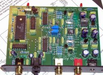
Hi Andy
Actually, that is a pic of Peter Daniel's DIBT - not mine. Too busy/lazy right now to open it up and take a pic. So - he has probably changed a few things.
Anyway - the point I was trying to get to is that it has been mentioned here that the external PS is "AC". However, I believe that it should be "DC".
Hi Fin,
I don't get to see the Forum so much nowadays, but someone has just pointed out your comments to me.
You are quite right about the DAC PS, and having looked into this again, what I said before appears to have been incorrect, for which I am sorry.
When I had this DAC in my possession it was over 15 yrs ago, and I was largely reliant on my memory together with my own hand-drawn PS details, because I was unable to find any official schematic for this DAC or PS at any time.
Unfortunately, due to a memory lapse, what I referred to earlier was my own 'upgraded' version which I constructed at a time when I almost gutted the entire DAC and rebuilt it with many new and different components inside.
Looking again at my original notes, the 'stock' A.A. "Power Station One" PS (apparently made by Engineering & Sales, Danville, Virginia, if this helps) stated " Sec. +/- 14V @ 400mA" and I am sorry if my earlier suggestion that it was 14V AC has caused any confusion here. I no longer know where that PS is, and I think I must have given it away.
Regrettably, I didn't make any note at the time of which was which polarity on the original jack pins and socket as I had changed this arrangement, but this should be clear from the orientation of the electrolytic caps which are on the original PCB.
Regards,
Hi Andy
I'm with you now. I will look closely at that when I open it up and start to play. Any other comments you have on this dac would be most appreciated.
Hi Bob
No problem with the AD/DC thing.....I just wanted to make certain.
I would be most interested in any other modifications you made....if you can remember that far back.
Probably the most important thing is - how did it sound? Is it worthwhile putting much effort into?
I have a Tentlabs XO DAC which can reclock the signals going to the dac chips etc......Does this little dac deserve that level of treatment?
Hi Fin,
Unfortunately I am really pressed for time right now, so this must be briefer than I would have liked.
Yes, there is huge potential for improving the DITB, but I soon found the original tiny enclosure to be a problem, which was why I subsequently re-built this unit in a larger more spacious box.
I don't now recall all the details, but the basic chips were not replaced, as they were considered quite good. The PS was completely replaced, a lot of local rail smoothing caps were added (now that there was adequate room for these), the regulators were upgraded and added to, and virtually all other caps were swapped using HQ electrolytics, some polystyrene bypasses, MIT RTX Multicaps, etc.
Damping many components, chips, and the PCB helped noticeably, as the original layout was so small and lacking in mass, and IIRC, I managed to separate (to a large extent) the analogue grounds from the digital grounds, which were originally 'shared' and therefore not ideal.
Many years later (maybe only 5 yrs ago) I came across an excellent article on modifying these DACS (most likely on the 'Net). This was very carefully and comprehensively written by an Amercan author, but I don't now recall his name. I was impressed with what he had tried, and much of it mirrored my own efforts, but on a quick search just now, it didn't come up for me. It would be worthwhile spending some time on this search, I believe, as you would learn a lot of good hands-on advice if you come across it.
However, another good article which I have just had a quick look at (mainly relating to this) did appear, and if you search under "all DACs are equal", I am sure you will enjoy the writings of DR Jon Wong on his experiences of modifying the DITB.
I hope this helps, and if anything else comes to mind soon, I will try to let you know.
Regards,
Thanks Bob - for all of this info.
Is this the document?
DIBT Mods...Audio Asylum
I've also been asking some questions in a few other threads:
AD1860 datasheet
Opamp upgrade for DITB DITB Mods
AA Dac Man
Is this the document?
DIBT Mods...Audio Asylum
I've also been asking some questions in a few other threads:
AD1860 datasheet
Opamp upgrade for DITB DITB Mods
AA Dac Man
Hi Fin,
That is not the same article I had in mind, and it was definitely not on Audio Asylum where I saw it.
However, interestingly I am 99% certain that it was by this same author (this was the name which earlier escaped me), and as this article is about "*modest* modifications to the DITB" he has possibly written some more somewhere else, of a more comprehensive nature.
It is just possible it was in Audio Electronics magazine, but I still think that it could have been on the 'Net, so it is worth persuing this. Unfortunately, when I read it, I no longer had the DAC in my possession and hadn't looked at the DAC for many years. So, apart from reading it out of interest, and being satisfied that we had independently trodden a very similar path, I had no real need to bookmark it.
The article I had in mind was in much more detail, with advice on cutting PCB tracks (IIRC) etc., and several diagrams showing how mods should be approached, which I think would be of more help to you, as it was specifically about the various mods he had made to the DITB. Generalised comments may be helpful, but if you are starting new with this circuit, the article I have in mind was more descriptive and took you through many individual steps, explaining the reasons for, and results of, many modifications.
I only wished that I had seen it before I carried my own modifications, as it would have saved me a lot of time in experimentation.
This article you refer to accepts that no real changes to the concept and enclosure etc. would be made, which, as I found, are severely limiting factors here, and restrict what can be done to the DITB.
It could well be that later on, the same author decided to revise his philosophy and go the 'whole hog' (as I did, of course!) and consequently carried out many more mods than described here in the AA article.
Whatever, all of us who appear to have played around with this amazing little DAC, have found that substantial improvements over the 'stock' DITB can be achieved, and it depends on how far one is prepared to go, and how much is available to spend on specialised parts in order to achieve one's ends.
Regards,
Bob.
Hi Bob
Thanks for all of this effort and detail....I'll keep looking for that detailed document with the extensive mods.....and now that I know the author...it should be easier.
I was initially just thinking of doing the modest mods and using it with my cheap pioneer DVD player to improved the sound from music DVDs etc. However, now you have me thinking that I should go the whole hog with it. Maybe a rebox, internal psu, and XO Dac is all worthwhile with this little one.
Did you employ any for of reclocking in yours?
I'll also need to look into the frequency of the crystal so as to get the correct oscillator from Guido Tent.
- Status
- This old topic is closed. If you want to reopen this topic, contact a moderator using the "Report Post" button.
- Home
- Amplifiers
- Power Supplies
- audio alchemy powersupply