You could possibly get the bost of both worlds by using the larger PIO cap and bypassing it with a smaller cap, like a teflon. That way you get the sonic fullness of the larger cap and the quickness of the teflon.
I know, there are probably a multitude of reasons not to bypass coupling caps, but if you are still taking sonics here then I would suggest you try it and see for yourself.
I know, there are probably a multitude of reasons not to bypass coupling caps, but if you are still taking sonics here then I would suggest you try it and see for yourself.
I agree that selecting a coupling cap is a compromise, buit there is a way out of this.
I've been messing around with some old Hammond organ amps recently. I've learned a little by studying their old design. The larger organ installations used "tone cabinets". Today we'd call these "powered speakers" Each was feed A/C power and three balanced audio signals. Inside the tone cabinet these was a three channel amp. It was not a stereo signal. There were three sets of speaker drivers and one amp for each set. Today we'd call this a "tri-amp" setup.
But Hammond was able to do something I don't think many audiophiles do today. They sized the coupling caps and designed the feedback network for each amp. In other words the bass and treble amps used identical circuit topologies but the component values differed, even the output transformers were designed for the frequency range.
I think Hammond's approach is the only way to get away from having to compromise between good bass and good highs on one amp. I wonder why we don't see this with DIY amps today? Yes we see bi-amps but people today tend to use a full range amp for both highs and lows - that is sub-optimal.
Not Armageddon, but start fooling with the rolloffs in a feedback amp and the Law of Unintended Consequences will almost certainly be invoked.
One example: take a look at the classic direct-coupled voltage amplifier to split load used in a bazillion amplifiers. If you separate their PS lines, this can (counter-intuitively) cause motorboating.
One example: take a look at the classic direct-coupled voltage amplifier to split load used in a bazillion amplifiers. If you separate their PS lines, this can (counter-intuitively) cause motorboating.
I recently tried .33 Russian PIO against 1u metalized poly as coupling caps after the concerta to the 6550 outputs. Modest resistive only feedback. After 50 hrs I could not tell the difference........ I would recommend the proper sized cap to couple the low frequency to minimize the induced distortion that the first stage must contorte with GNFB. Too small the first stage must overreact, tooo large you can suffer blocking distortion... DO the math and select based on the f3 that you want to pass.
You should size your coupling caps for a 3dB point a decade below the lowest operating frequency. There are at least two reasons for this.
1. Frequency response only starts to change about an octave above the turnover frequency but phase begins to change noticeably a decade above.
2. Many capacitor types distort if they have significant ac voltage across them (and not just electrolytics). At normal frequencies, coupling capacitors have no ac voltage across them but at low frequencies as their impedance begins to increase so does the voltage across them
Cheers
Ian
.......I would recommend the proper sized cap to couple the low frequency to minimize the induced distortion that the first stage must contorte with GNFB. Too small the first stage must overreact, tooo large you can suffer blocking distortion... DO the math and select based on the f3 that you want to pass.
Your'e nearly there.......but with gnfb you left the nasty output tranny out of the circuit......and of course there's circuit gain. In most cases the 1st stage cap values in p-p are quite low for a reason......the o/p tranny b/w and the relevant Q & phaseshift. So one designs around the loop transient response which often violates the -3dB rule.
Assuming an excellent power supply, one can prove this on gnfb amps by increasing the coupling cap values of all stages til circuit oscillates. Reduce all values til sound is without body and thin. There is a middle ground.
Assuming a good layout and the values optimised, a circuit using gnfb should be able to accept a considerable amount of gnfb before instability occurs at both ends of the frequency spectrum but often hard to acheive.
Remember, the LS system also has a design Q factor, so the K transient factor of the amp effectively should fit in too.
That's the reason why similiar rated output transformers from two differing manufacturers most likely need interstage and 1st stage phase correction and interstage capacitor values tweaks.
For those physics apted, study the Basic Transfer System of a phase locked loop, it has all the ingredients for ascertaining the correct K damping of a gnfb tube amplifier, and it works. It's not rubbish...get it correct and the power handling with lowest frequency intermodulation performance is excellent. It shows that for proper stability there is an optimum value for coupling caps vs. gain and frequency range. Determining the output transformer inductance is the achilles heel, mostly poorly defined and circuit has to optimised on the bench.
The damping factor that appears across the output terminals is the output winding resistance divided by the amount of output volts reduction when global nfb is applied. 20dB gnfb = 10Xvolts; so assuming a secondary output resistance of 1 ohm then with gnfb becomes 1/10=0.1 Ohms effective. One will need this low output Z when complex LS crossovers are used.
This is the reason why designing proper feedback amplifers is alot more complicated than at first sight.
richy
Attachments
Last edited:
ruffrecords is generally correct, but with one small proviso. Something must set the LF rolloff point. If you don't set it with a capacitor, it will either get set elsewhere or in the output transformer. Often best to set it early on with a smallish cap, so you don't get LF distortion in later stages where the signal is bigger.
Often best to set it early on with a smallish cap, so you don't get LF distortion in later stages where the signal is bigger.
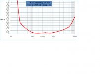
Decoy....reducing the coupling caps in gnfb amps and with a bigger signal in o/p tranny generally results higher F2 harmonic. Try it. Graph shows it.
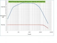
Reducing coupling cap value in early stages reduces loop gain at the lower f end so effective gnfb dB value has dropped.
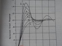
Typ loop gain graph characteristic of a 7W 3 stage amp. Notice the effective gnfb of 11.5dB at 20Hz with 10nF concertina coupling caps. With 50nF caps the line would be much straighter but the circuit has considerable transient overhang with the lower thd because loop gain holds up which forces phase towards oscillation. The side effect of excess gnfb is a sluggish one note transient response......bad for quality as the speaker cone is held out longer on a transient excursion creating a reduction of other audible frequencies. Worse is extreme values causing blocking.
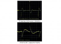
The distortion results at the low F end is shown in the combi graphs......
Which one would be chosen ? The one with the better transient recovery i.e 10nF at the expense of increased low freg thd sounds better and the amp can be pushed harder.. Actual optimum circuit transient response occurs with an 8nF cap so 10nF was chosen.
For those who mention that some tube amps display the LF squarewave with an inherited slant away from a true squarewave form is quite correct.....something has to give for the "Q" to be optimised.
Exactly the same procedure for high power amps, even more important when the output stages are pushed to the extremes.
richy
Attachments
I think the original question was about capsize/sonic
I´ve used smaller caps parralleled insted of one and can´t find any downsides think i even like it better, but my ears are the leadversion not gold.
My vote goes to the smallest size.
If several types and sizes in parallel the different "delay" in the caps might be a problem ?
That´s for more educated people to investigate.
")
?flatheadmurre said:If several types and sizes in parallel the different "delay" in the caps might be a problem ?
Omitting a cap often means adding something more complicated, like a DC servo, or propagating bias problems from one stage to the next so can be a poor tradeoff. Omit caps which are not needed; include the rest.Tony said:and the best cap is.....no cap....if you can get away with it...
Not worth updating and modifying amp caps before updating all those low quality caps often found in LS crossover networks......some of these are atrocious dual polarity electrolytics and other types of inductors that colour the sound.
Still, I have an old 25W 12" Dual paper cone speaker of the 1960's without a crossover network in a reflex cabinet and sounds wonderful.
richy
Still, I have an old 25W 12" Dual paper cone speaker of the 1960's without a crossover network in a reflex cabinet and sounds wonderful.
richy
- Status
- This old topic is closed. If you want to reopen this topic, contact a moderator using the "Report Post" button.
- Home
- Design & Build
- Parts
- Audible benefits of larger coupling caps than required?