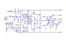
This is the schematic of a consumer amplifier .
Problem of the specific amplifier is that if rail drops lets say to 2/5 of rated voltage amplifier oscillates , bias is increased by a factor of 100 and smoke !!! outputs and obviously zobel resistors .
Obviously no one expects amplifiers to be stable at 2/5 of rated rail voltage One may expect the amplifier not to be functional , but oscillation and self destroy is another issue .
Problems are :
At the service center is a problem to repair the amp with a classic procedure IE repair and use a variac to slowly build the voltage while observing amplifier's operation .
At 2/5 of rail voltage amplifier seriously oscillates and at the specific point at no load no signal conditions a few seconds at this voltage will be enough to destroy the amp I wonder what will happen if this happens with a load connected .Remember that @ 90Vac mains, speaker relay remains on.
In the specific amplifier there might be AC loss detect circuit to shut down the speakers bellow 90VAC ( with mains 230V ) but this will do nothing to prevent the amp from smoke .
Farther more for this amplifier there is no standby circuit to prevent AC loss at this point and shut the total amplifier down to prevent the problem .
Obviously expecting mains to fail from 230 to 90v is a chance one in a million though just a couple of seconds in this voltage will be more than enough to blow the amp totally .
Kindest regards
Sakis
Enjoy
Attachments
Last edited:
The problem is that when voltage is reduced the input differential will stop working (and driving the VAS to control the DC output level) before the VAS CCS stop conducting, the design of the CCSs is poor in this respect and the "designer" didnt take account of all possibles conditions of operating voltages, namely when it s powered on and off.
There would be more Miller capacitance between the collector and base in Q207 than in C205. 1.8 pF is almost as bad as zero for a Miller Compensation capacitor.
The Miller capacitance in Q207 will vary according to the voltage at the collector and I cannot see 1.8 pF having the necessary dominant effect.
Some component values are not clear in the diagram it may be worth checking values of the components on the board to see if decimal points are in the right place.
a fine notice mjona thanks but if 1.8pf is not efficient enough as a miller cap then the amplifier will also oscillate at full rail voltage which clearly doesn't happen here
In a minute i will check BOM and the actual circuit and get back to you .
Also TBH i dont know how the miller cap in this circuit will behave at the point that voltage is dropping and if this is the issue why is driving the amp to that much oscillation .
Kind regards
Sakis
In a minute i will check BOM and the actual circuit and get back to you .
Also TBH i dont know how the miller cap in this circuit will behave at the point that voltage is dropping and if this is the issue why is driving the amp to that much oscillation .
Kind regards
Sakis
Hi Sakis,
In fact, "parasitic" capacitances of active devices pretty much depend on collector voltage (in case of BJTs), so it looks like the amplifier works at the edge of stability with full rails, but reach the limit with lower rails.
See a good article here - formulas (5.6.4) and (5.6.5) here:
Bipolar Junction Transistors
I agree with Mjona - 1.8pF as a Miller cap - something really ... how to say") ... almost nothing. So, as the rails decrease, the amp may start oscillating just because the operating points are moved, leading to changing transistors' internal capacitances.
... almost nothing. So, as the rails decrease, the amp may start oscillating just because the operating points are moved, leading to changing transistors' internal capacitances.
No lead compensation cap (in parallel with R210) and/or any RC combinations - also suspicious. In many cases they are used to correct the loop phase response curve, setting the phase margin high enough for unconditional stability.
Certainly an "opinionated" design
In fact, "parasitic" capacitances of active devices pretty much depend on collector voltage (in case of BJTs), so it looks like the amplifier works at the edge of stability with full rails, but reach the limit with lower rails.
See a good article here - formulas (5.6.4) and (5.6.5) here:
Bipolar Junction Transistors
I agree with Mjona - 1.8pF as a Miller cap - something really ... how to say
... almost nothing. So, as the rails decrease, the amp may start oscillating just because the operating points are moved, leading to changing transistors' internal capacitances.No lead compensation cap (in parallel with R210) and/or any RC combinations - also suspicious. In many cases they are used to correct the loop phase response curve, setting the phase margin high enough for unconditional stability.
Certainly an "opinionated" design
The collector to base diffusion capacitance is inversely in proportion to the square root of the voltage applied to the collector so with full rail voltage and no signal the voltage drop via the collector load will be at its' lowest value and the voltage seen at the collector at its' highest value. Thus the diffusion capacitance will be at the lowest value - not enough that 1.8 pF is any help here.
It would be more stable to some degree with lower voltage rails. Your variac has demonstrated this to a point where things take off. You could could try progressively increasing the value of C.dom until you can get to full rail voltages where you can look at the waveforms with your 'scope to see how much further you need to take this - and any other stability measures like a lead capacitor in the feedback resistor or an RC step version of the latter if the system is not unity gain stable.
It would be more stable to some degree with lower voltage rails. Your variac has demonstrated this to a point where things take off. You could could try progressively increasing the value of C.dom until you can get to full rail voltages where you can look at the waveforms with your 'scope to see how much further you need to take this - and any other stability measures like a lead capacitor in the feedback resistor or an RC step version of the latter if the system is not unity gain stable.
Last edited:
If your rail voltages at the critical point of full blown oscillation are less than 20 volts (the zener reference) then the reference for the input pair and voltage stages is suspect. You seem to be having a current starvation point that changes abruptly at some point when the rail voltages are increased - counter productive to the use of your variac.
If so, I suggest fitting a pair of wire-wound resistors of 100 R suitable wattage in the supply rails and see if you can press through the critical point with your variac.
As far as the 1.8 pF capacitor is concerned I think there would be some capacitance in the circuit board traces - it could be these have been enlarged.
If you can get to full rail voltage you can use a test signal and scope to see what is going on in the way of oscillation.
If you can measure the respective collector voltages of Q207 at full rail voltage and the critical point, the square root of these two might be useful information in relation to a starting point for increasing the C.dom value.
If the voltage at the collector is not too high as to be a danger you could try putting your finger between this and the base. To see if this additional capacitance has any impact on the waveform.
Ok got the message thank you so far i will take it from here
Both miller behavior and reference is now understood
Putting my finger on it ? No this is not going to happen I don't like to approach electronics like that ( not afraid of rail voltage ) more afraid to destabilize the amplifier
I will go by changing miler caps
and also monitor the current source behavior
Thanks so far people
Kind regards
Sakis
Also might be related, look at the bias spreader. There is something really wrong there - capacitor between B-E (!) rather than across C-E or C-B. Also, the trimmer is between C and B which means if it goes open, infinite bias. It almost look like it was designed for a PNP transistor, with C and E exchanged on the schematic. At some supply voltage the current source for the VAS and the B-E cap might interfere to result in a huge bias current.
The CCS built with Q203 should provide about 5mA but given that there s a 5K resistor in serial and that it use a 20V zener reference, and that the biased zener D204 is also 20V then about 65V are necessary to get it act as a CCS, that is +-32.5V supply voltage to get to this operating point.
Along with the other "details" pointed by some members this look like a quite randomly designed amp, i will add that the LTP current is about 2mA and that the 1K collector loading imply that there will be 0.7mA in a tail and 1.3mA on the other.
Along with the other "details" pointed by some members this look like a quite randomly designed amp, i will add that the LTP current is about 2mA and that the 1K collector loading imply that there will be 0.7mA in a tail and 1.3mA on the other.
Last edited:
The LTP current is actualy balanced because the VAS degeneration is so high that it raise the base voltage at the convenient value, but that s a poor design anyway, the lowish Cdom is of no effect, it should be raised by 10x, as it is currently there should be a huge peak at about 5MHz in the frequency response, and of course a consequent lack of stability.
With a few bills you can get people saying very nice things about one s product, what is sure is that those magazines have no regard for their readers money.
Guys ...
This is a commercial design existing in the market for i think 5-7 years ....Some magazines wrote down some very nice things about the way it sounds ....
Are we missing something ?
With a few bills you can get people saying very nice things about one s product, what is sure is that those magazines have no regard for their readers money.
- Status
- This old topic is closed. If you want to reopen this topic, contact a moderator using the "Report Post" button.
- Home
- Amplifiers
- Solid State
- Attention please oscillation