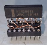
I've had this 1979 amp and preamp pair for several years now, and I've often wondered if i can replace the near prehistoric "stereo preamplifier" ic with a modern opamp.
It sure looks to me like a dual opamp with external compensation and offset zeroing, but the datasheet is less detailed than we expect these days. For example, it says it has a differential amplifier, and does not specify which input is inverting or noninverting.
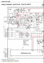
I've attempted to draw a simplified schematic, using an ne5534 as a stand-in for 1/2 of the ha1452w, and without the rest of the preamplifier input (a jfet pair) or the tone controls, etc.
Does this make sense to anyone?
I attempted to air-wire an adapter to an njm2068L but this just results in a hum at the output.
.JPG")

It sure looks to me like a dual opamp with external compensation and offset zeroing, but the datasheet is less detailed than we expect these days. For example, it says it has a differential amplifier, and does not specify which input is inverting or noninverting.
I've attempted to draw a simplified schematic, using an ne5534 as a stand-in for 1/2 of the ha1452w, and without the rest of the preamplifier input (a jfet pair) or the tone controls, etc.
Does this make sense to anyone?
I attempted to air-wire an adapter to an njm2068L but this just results in a hum at the output.
Attachments
From what I can see,
pin 6 non-inverting,
pin 5 inverting,
pin 2 output,
pin 4 compensation,
pin 1 just needs decoupling
You don't need to emulate pins 1 and 4 of course.
R622 is odd, it would be acting to increase distortion by throwing away open-loop gain.
With a JFET opamp you can probably lose C607/C614 and the DC feedback path (R608/C605/R609), as there's a DC path through the tone stack. However the tone defeat switch needs to be make-before-break for this to be safe.

From what I can see,
pin 6 non-inverting,
pin 5 inverting,
pin 2 output,
pin 4 compensation,
pin 1 just needs decoupling
You don't need to emulate pins 1 and 4 of course.
R622 is odd, it would be acting to increase distortion by throwing away open-loop gain.
With a JFET opamp you can probably lose C607/C614 and the DC feedback path (R608/C605/R609), as there's a DC path through the tone stack. However the tone defeat switch needs to be make-before-break for this to be safe.
You were correct. I had initially guessed wrong when picking the inverting and noninverting inputs in the hitachi schematic.
Revised hacky air-wired adapter is working great. Now i need to produce some gerbers and send out for boards so i can try some so-8 parts.
And i should really re-acquaint myself with RMAA so i can measure the difference.
Sent gerbers to LCSC last night. Yes, I noticed the little unnecessary jog in the trace next to pin 5 as soon as they confirmed my order. So it goes. Also submitted some designs for SIP parts and a sip-to-dip adapter, also with accommodation for power bypass and bandwidth limiting caps (smd cap on the back of the board for the so-8 adapter).

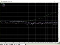
Preliminary RMAA results. Did this with an AMB Labs y2 DAC hung off USB for the output because i am tryin'a figure out how to configure patchmix so i can do the whole test with my trusty e-mu 1616m.
Looks like the IMD is pretty bad with the original hitachi part, all three of the different opamps i have tried on the adapters are much better in that regard.
Also, this preamp has a pretty steep treble roll off i would like to modify out, but that's another thread.
Looks like the IMD is pretty bad with the original hitachi part, all three of the different opamps i have tried on the adapters are much better in that regard.
Also, this preamp has a pretty steep treble roll off i would like to modify out, but that's another thread.
Attachments
The new schematic has a few serious errors. C605 and R608 are shorted for instance and R608 should be connected differently to the opamp. C607 is 47 µF not 4.7 µF. Please keep to original schematic except for C603 value which is way too small. For better performance with modern opamps many resistor values are too high.
Last edited:
Huh, wonder why i can't quote you.
Yes i have made an error with regard to c605 and r608 in that schematic. Thank you for pointing it out.
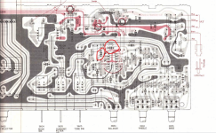
C607 has an incorrect value in my re-draw of the schematic but i believe i made the correct replacement on the board. You can see the box wimas in the picture, kind of a waste of money for a loudness filter that i am embarrassed about I guess. You can see them here in the graphic of the board layout (as seen from the copper side in the service manual).
I will double check what is in the c607 position on the board post-recap.
Yes i have made an error with regard to c605 and r608 in that schematic. Thank you for pointing it out.
C607 has an incorrect value in my re-draw of the schematic but i believe i made the correct replacement on the board. You can see the box wimas in the picture, kind of a waste of money for a loudness filter that i am embarrassed about I guess. You can see them here in the graphic of the board layout (as seen from the copper side in the service manual).
I will double check what is in the c607 position on the board post-recap.
Attachments
Last edited:
Yeah this device was not designed for high sound quality it seems. Like many devices of that time it predominantly has a lot of features regarding switching possibilities for tape decks etc. Anyway I would use at least 1 µf for input caps, lower the input impedance in accordance and to todays standards and use only one feedback loop in lower resistance values.
BTW R622 is 10 kOhm in the schematic. Could you check how it is connected in reality as it seems to be wrongly drawn? I think it is connected to the feedback resistor and the other side to Audio GND.
You can/should omit C606 with modern opamps.
BTW R622 is 10 kOhm in the schematic. Could you check how it is connected in reality as it seems to be wrongly drawn? I think it is connected to the feedback resistor and the other side to Audio GND.
You can/should omit C606 with modern opamps.
Last edited:
I checked the board and yes, I did use 47uf nichicon kz at the c607 positions.
I will have to take a look at R622 on the physical board. That is one aspect of what I don't understand in the way the original schematic is drawn. C605 is another.
C603 seems to be the input coupling cap and i had wondered if it is too small, but the way the schematic is drawn suggested to me that it formed a filter primarily with R607. I certainly have 1uf film caps i can put in that position.
pins 3 and 12 have no connection on the adapters i had made. I'll remove the capacitor eventually. Short term i would like to be able to put the ha1452w back in to make comparison measurements, but eventually there will be no reason to have it handy.
There appears to have been some rework in this unit. I know it had some aftermarket repairs because the original fixed output cable had been replaced with some rca jacks that were poorly installed. There are also some mylar caps tacked to the board next to the RIAA stage, and one of the ribbon cables has two wires quite deliberately cut. It looks as though those connections were re-done with a shielded cable that may or may not be original, as the connection from the input jacks to the board in the HMA-6500 has been done with the same cable.
There are also some mylar greenies tacked to the back of the board in the RIAA section. I was born too late to have much vinyl so i am not really that concerned about the RIAA preamp.
I know the resistor values are designed for an opamp with high input currents. Once i better understand the design i would like to improve that.
Last edited:
Updated my drawing with some mistakes fixed and the tone stack added.
R622 really is used in this way, and that doesn't make sense to me. I also don't understand why C605 and R608 exist.
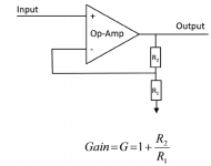
So, because of my lack of understanding, I am not sure what the gain of this circuit is. But I'd prefer to alter the circuit for more normal values for an lme49720, or for a fet-input opamp.

R622 really is used in this way, and that doesn't make sense to me. I also don't understand why C605 and R608 exist.
So, because of my lack of understanding, I am not sure what the gain of this circuit is. But I'd prefer to alter the circuit for more normal values for an lme49720, or for a fet-input opamp.
It seems you'll have to make a choice to abandon the tone control circuit (or to adapt it). I can not advise on Baxandall and certainly not when it is in the feedback loop as done here with all the added tolerances of the used parts and potentiometers. Despite having symmetrical power supplies the device has coupling caps everywhere probably because that HA1452W opamp did not behave very well with regards to DC offset etc. C605 is in a DC feedback loop.
With todays opamps you should remove R622 and R609, bridge the PCB pads of C605 (and remove C605), change R608 to a value for the gain you desire in combination with a new feedback resistor for that gain between output and inverting input. Or: remove C605, remove R608 and solder a new resistor from the R608 PCB pad connected to the inverting input and the other end to GND of C605, replace R609 for a normal value and connect the left side to the inverting input. Same in the other channel. I would remove C607 and C614.
You will have better performance definitely but what about making a new device that is OK straight away and leave this device original?! A low gain opamp based preamp/buffer or DCB1 with basic but good quality source selection and volume control the right way is nice to do. I am quite sure the Mezmerize will outperform this device big time.
Last edited:
You could remove R622 and R609, bridge the PCB pads of C605 (and remove C605), change R608 to a value for the gain you desire in combination with a new feedback resistor for that gain between output and inverting input.
Or: remove C605, remove R608 and solder a new resistor from the R608 PCB pad connected to the inverting input and the other end to GND of C605, replace R609 for a normal value and connect the left side to the inverting input. Same in the other channel. I would remove C607 and C614. R607 can be 475 kOhm, C603 1 µF film.
10 kOhm for the R2 in the example and 4.7 kOhm for R1 are OK when the Baxandall is not used.
Attachments
Last edited:
I have a little Hitachi receiver from the good old days, the Hitachi SR302. It uses this scarce Hitachi H1452 dual op amp. I don't like sole source parts like this Hitachi H1452 in my receiver and never use sole source parts in design. It sounds like the H1452 used in the preamp here discussed has poor IM performance. A plug in replacement board would solve the performance and scarcity problem, so I wonder if the board design was implemented on a production basis. I did lay in a stock of the proprietary H1452 for my needs, but I would love to replace it with a better performing assembly which would plug in to the same socket. Did someone make this available?
- Home
- Source & Line
- Analog Line Level
- Attempting to make sense of the HA1452W IC in my vintage Hitachi HCA-6500 preamp