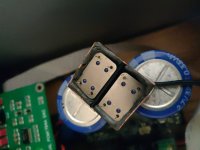
I do it this way. copper shielding with earth and secured all around with Blu Tack. a small piece of foam at the top inside so that the clocks do not make contact with the outside off the copper shield.Can you post a pic of this? Just trying to get an idea on how to dampen the clocks and or shield them
I use ACCUSILICON clocks.
Due to the weight of copper and blu tack it remains nicely pressed down.
You could of course also secure the bottom with blu tack, I didn't think this was necessary.
Attachments
Last edited:

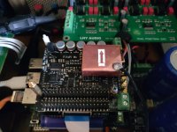
Thanks you very much, @Gabster 2000 , it appears you were right! I changed out the connectors on my dc cables and everything is now working perfectly. My system has never sounded so good. Accuphase E4000 integrated amp with Sonus Faber Auditor M SE speakers. Heavenly!It seems the issue lies with the type of connectors you're using when mounting them to the case. Based on what I see, your case is attached to the negative pole of your Raspberry Pi, FifoPi, etc. Then, you connect your input power to the same ground, effectively connecting your Linear Pi input to the output.
so all the blue lines terminals are connected see photo attached. I am surprised you have not damaged anything.
I recommend using different connectors altogether for all components, or at the very least, changing all your power input connectors so they do not connect to the ground. It's important to note that your connector's metal screw is connected to one of the two wires of the input (black wire ), if the metal screw is not connected to anything then ignore all this.
hope this help you see what I am trying to say. View attachment 1290045
@NeoTheOne - I believe that is the case. I am planning to use both the HdmiPi Pro II and the ES9038Q2M at the same time (which I have seen others do) and this is the same situation.
How thick is that copper?I do it this way. copper shielding with earth and secured all around with Blu Tack. a small piece of foam at the top inside so that the clocks do not make contact with the outside off the copper shield.
I use ACCUSILICON clocks.
Due to the weight of copper and blu tack it remains nicely pressed down.
You could of course also secure the bottom with blu tack, I didn't think this was necessary.
FiFoPi Q7 can provide the output signal to two devices at the same time. This is when they need MCLK. I have even made it work with 3 devices taking I2S signal from GPIO connectors to the third DAC that does not need MCLK.Can FifoPi Q7II power both HDMI ProII and TransporitPi AES at the same time? If I connect the 2 MLCK outputs for FifoPi Q7II to TransportPi AES and HDMI ProII will the outputs be available simultaneously on both TransportPi AES and HDMI ProII ?
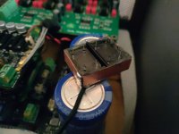
This is how I have it in my stack. Moongel pad is under SC-Pure and a Sorbothane pad is above, pushed down by a Dual Mono DAC board.Can you post a pic of this? Just trying to get an idea on how to dampen the clocks and or shield them
Attachments
Is it safe to add Moongel damper pad like this between the FifoPiQ7 II socket and the Purepi clocks? could this harm the board and the clocks with such things?This is how I have it in my stack. Moongel pad is under SC-Pure and a Sorbothane pad is above, pushed down by a Dual Mono DAC board.
@weust a very long time, I have had it in an audio research preamplifier for 10 years.
is the same name blu tack.
https://www.hildebrandpapier.nl/kan...-en-bevestigen/plakgum-blu-tack-105-gram.html
putty is about the same and I also used it to secure the clocks.... it is a lot darker in color.
https://www.etsy.com/nl/listing/1444520483/kunstgum-staedtler-karat-kneedbare-putty
is the same name blu tack.
https://www.hildebrandpapier.nl/kan...-en-bevestigen/plakgum-blu-tack-105-gram.html
putty is about the same and I also used it to secure the clocks.... it is a lot darker in color.
https://www.etsy.com/nl/listing/1444520483/kunstgum-staedtler-karat-kneedbare-putty
Attachments
Regarding the damping of SC-pure clocks.
Has anyone tried using the form op-amp and similar are delivered in? Or maybe the form from the SC-pure?
@Spacejack
Are you using the softest sorbothane version of the one you linked to?
Has anyone tried using the form op-amp and similar are delivered in? Or maybe the form from the SC-pure?
@Spacejack
Are you using the softest sorbothane version of the one you linked to?
Yes@Spacejack
Are you using the softest sorbothane version of the one you linked to?
I am narrowing down my power supply design for my streamer/dac build. As I mentioned in a previous post, I have enough space for 14 3000F caps, and have a custom transformer with seven independent secondaries to power up to seven UcPure supplies, four of which can provide 1.5A charging current and three 3A. For the first option below, I will parallel two of the 1.5A secondaries to create a single 3A charging circuit.
I'm looking at the following two options, the main difference being the power for the ReceiverPi DDC and FifoPi dirty side.
iFi SMPS for RPi 4
LinearPi + UcConditioner for IsolatorPi II, HdmiPi Mk II, ReceiverPi DDC, FifoPi Q7 Dirty side
UCPure (4 3000F Caps) (3A) for FifoPi Q7 clean side.
UCPure (3A) charging for HdmiPi Pro II
UCPure (3A) charging for ES9038Q2M DVCC/VCCA
UCPure (3A) for ES9038Q2M AVCC
2x UCPure (1.5) for OPA861
OR
iFi SMPS for RPi 4
LinearPi + UcConditioner for IsolatorPi II, HdmiPi Mk II
UcPure (1.5A) for ReceiverPi DDC, FifoPi Q7 Dirty side
UCPure (3A) for FifoPi Q7 clean side.
UCPure (1.5A) charging for HdmiPi Pro II
UCPure (3A) charging for ES9038Q2M DVCC/VCCA
UCPure (3A) for ES9038Q2M AVCC
2x UCPure (1.5) for OPA861
Opinions please.
No.If a build uses multiple LifePO4 Mini 3.3V to power various components independently what would be a good way to power them? Too many USB adapters. Can we use something like this?
The manual for LifePO4 Mini 3.3V clearly states: "The USB-C power adapter has to be independent and cannot be shared with other devices."
Many (if not most) USB-C chargers with several ports work in such a way that when you connect/disconnect (or turn on/off) a device connected to one of the ports, the charger will switch off the power on all of the USB-C ports, and turn them on again in a short moment. This can lead to several problem scenarios beyond the length of this post.
I also recommend using a USB-A to USB-C charger/cable for the current generation of LifePO4 Mini 3.3V. USB-C to USB-C requires a PD protocol to turn 5V, which the current generation of LifePO4 Mini 3.3V does not support. The next upgraded generation should support it.
You could use a charger like this: https://a.co/d/iCr6aRQ
I use those. A separate one for each LiFePO4 Mini 3,3V
- Home
- Source & Line
- Digital Line Level
- Asynchronous I2S FIFO project, an ultimate weapon to fight the jitter