ReceiverPI no output on SPDIF
HI All,
hope this is the right thread for this.
I'm having a problem with my new stack PI4>ReceiverPI>FIFOPI>TranceiverPI
I have had it playing fine today with input selected by switch (pin 19/20 , just powering my CD selects SPDIF RCA) it was playing fine, after switching back and forth several times between inputs PI / Spdif RCA from CD, then on switching back to CD....no sound.
Nothing was changed just switching inputs.
PI plays fine and sounds great
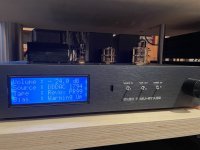
Spdif on output --- leds on ReceiverPI blue RCA lit and blue lock lit,
--- leds on FIFO red empty lit amd both xo leds flashing alternatly.
I hope someone can help.
Cheers Steve
HI All,
hope this is the right thread for this.
I'm having a problem with my new stack PI4>ReceiverPI>FIFOPI>TranceiverPI
I have had it playing fine today with input selected by switch (pin 19/20 , just powering my CD selects SPDIF RCA) it was playing fine, after switching back and forth several times between inputs PI / Spdif RCA from CD, then on switching back to CD....no sound.
Nothing was changed just switching inputs.
PI plays fine and sounds great
Spdif on output --- leds on ReceiverPI blue RCA lit and blue lock lit,
--- leds on FIFO red empty lit amd both xo leds flashing alternatly.
I hope someone can help.
Cheers Steve
Hi,
Also thank you from my side to Ian for providing the sinepi for testing!
Nice to read the findings of Doede
I also mounted the sinepi into my new dac. It is too early for me to compare the differences because I am running a complete new dac since a week, so everything sounds different.
The mounting is certainly more stable than the doublers from Andrea, especially with the reclockpi on top it is fixed quite well.
I just want to let everything, including the sinepi, run in for a while before I judge the performance. But I already can say that the sinepi does not seem to hold anything back as the sound is already very involving!
The setup is as follows:
-Allo Usbridge Signature.
-shield
-fifopi Q3
-sinepi
-reclockpi
Power to fifopi-sinepi-reclockpi is by 3,3v Linearpi and UcConditioner.
The I2S data is fed to an I2S-SIM converter that also makes balanced datastreams for each channel to be used by 2 balanced TDA1541A dacs, the IV conversion is done by Sowter 1465 transformers with the IV resistor on secondary side.
I will report my findings at a later stage!
Attachments
HI All,
hope this is the right thread for this.
I'm having a problem with my new stack PI4>ReceiverPI>FIFOPI>TranceiverPI
I have had it playing fine today with input selected by switch (pin 19/20 , just powering my CD selects SPDIF RCA) it was playing fine, after switching back and forth several times between inputs PI / Spdif RCA from CD, then on switching back to CD....no sound.
Nothing was changed just switching inputs.
PI plays fine and sounds great
Spdif on output --- leds on ReceiverPI blue RCA lit and blue lock lit,
--- leds on FIFO red empty lit amd both xo leds flashing alternatly.
I hope someone can help.
Cheers Steve
"leds on FIFO red empty lit amd both xo leds flashing"
It means FifoPi can not figure out which XO match the input signal frequency
Two possible reasons
1. Check if XOs are fit well into the socket
2. FifoPi clean side power supply
I would suggest
1. Try different spdif source
2. Try RPi only without ReceiverPi
Please let me know if you have an update.
Ian
Thanks Ian, for letting me try the SinePi
I had it powered for a week or so to make sure it is burned in.
Build quality is great as we are used from your products.
I have been doing some first listening with the same setup I have been using for all the clock tests. This is not the top-top-top possible version of a setup. The idea behind is, that also in a somewhat more normal DAC situation things should make a difference (or not)
I will write some more on my Blog Site later, but just wanted to give this first impression. Which of course is my personal experience in my system.
Long story short, besides the mechanically benefit of the SinePi versus the sine-square board from Andrea, it also sounds a little bit more spatial and let the instruments and voices tone a tad more natural. I have been going back and forward several times and it was recognizable on different tracks. The difference is small. I cannot repeat enough that this is not about high-end versus shower radio. Both are fantastic and I could easily live with both. Like so often, if by some magic the sine/square converters would be changed without me knowing and I would listen to my setup a few days later I most likely would not jump up like "what the heck happened !" but instead just enjoy the music
But as it is in our hobby, if in a direct comparison you lean toward option XYZ, you just let that option sit in the final setup and take any further tweaking from there. And that is also the case with the SinePi. Now it is there it can stay.
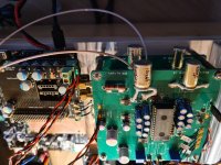
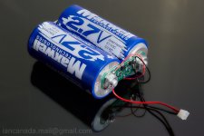
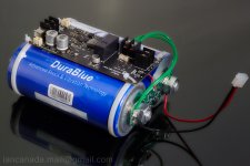
Some pictures of the setup. As you can see I made a poor mans A123 Battery supply with the EATON Ultracapacitor Bank to power the Andrea 5.6MHz clock (In the background you might notice a Neutron 3 11MHz clock - in my blog later more)
I could not yet try if there is a cross influence when the 6,1MHz clock is connected to the other SMA connector, for the simple reason I cannot get the 6,1MHz clock to work. Andrea is already trying to help me out (Thanks for support Andrea !) so hopefully that will be tested as well soon.
Hi,
Also thank you from my side to Ian for providing the sinepi for testing!
Nice to read the findings of Doede
I also mounted the sinepi into my new dac. It is too early for me to compare the differences because I am running a complete new dac since a week, so everything sounds different.
The mounting is certainly more stable than the doublers from Andrea, especially with the reclockpi on top it is fixed quite well.
I just want to let everything, including the sinepi, run in for a while before I judge the performance. But I already can say that the sinepi does not seem to hold anything back as the sound is already very involving!
The setup is as follows:
-Allo Usbridge Signature.
-shield
-fifopi Q3
-sinepi
-reclockpi
Power to fifopi-sinepi-reclockpi is by 3,3v Linearpi and UcConditioner.
The I2S data is fed to an I2S-SIM converter that also makes balanced datastreams for each channel to be used by 2 balanced TDA1541A dacs, the IV conversion is done by Sowter 1465 transformers with the IV resistor on secondary side.
I will report my findings at a later stage!
Hi dddac,
Hi Supersurfer
You did great jobs on evaluating the SinePi. Thank you so much for your works and the experience sharing with the community.
I'm so glad that they work well in your system and with some improvements.
The finial version will be V8. That means the design was revised seven times before I finalize it. Too many considerations in it but I have to say it's a really interesting project. I hope you will have more discovery while working with it.
I have one thing highly recommend to you which the is 3000F ultracapacitor power supply for SinPi/FifoPi clean side.
You can just simply try a 3.3V pre-charged 3000F pair as FifoPi clean side/SinePi power supply. It can last at least 5 hours before drop to 3V.
I believe you will have a new surprise. The ultra capacitor power supply won't disappoint you.
Or, for a well designed pure ultra capacitor power supply, you can wait for my UcPure (in default 3.3V configuration). I'm trying to make it available soon.
Looking forward to your new updates.
Thanks again
Ian
Attachments
Thanks for the feed back. I see Drixo clock with SOTA power supply, FIFOPi, no ReclockPi into DDDAC. May I ask what is downstream electronics and speakers? Just curious. Your test makes sense as it's consistent with your other clock tests. Then I think we'll hear from SuperSurfer which may be in his main system and those two plus Ian's report will give a comprehensive set of feedback.
sure, here you go:
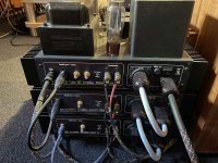
After the DAC the signal follows:
Preamp: Cleo7 (Tube amp Mu stage with 6N30P) Built by me - see my blog site
3 Amplifiers (first two designed and built by me):
KR 300B XLS SE amp for all above 200Hz - passive 12dB filter - 15 Watt
Tumos class A Amplifier for 0-200Hz - passive 12dB filter - 40 Watt
Subwoofer amp (UCD 180Watt) till 60 Hz with 48dB/oct: Behringer digital cross over compensating bass fall off in closed enclosure - Sub goes down straight till 25Hz
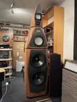
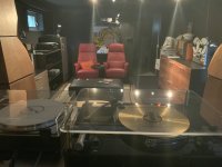
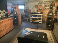
Speakers "Gydinel" (see DDDAC 2000 vintage website for project description) are a kind of Avalon Sentinel clone with Ceramic units from Thiel and their diamond tweeter
see some pics below (I just realize it is time for some dusting off
 )
):
Attachments
-
 2021-09-08_08-47-17_IMG_5482.JPG373.5 KB · Views: 293
 -
 2021-09-08_08-44-49_IMG_5479.JPG401.6 KB · Views: 263
 -
 2021-09-08_08-45-20_IMG_5480.JPG350.6 KB · Views: 254
 -
 2021-09-08_08-46-54_IMG_5481.JPG261.2 KB · Views: 276
 -
 DDDAC Music and Movies room 2020 - 2.JPG524.7 KB · Views: 257
 -
 DDDAC Music and Movies room 2020 - 1.JPG597.2 KB · Views: 264
Last edited:
@dddac
Awesome! That's the only word I can think of for now!
Your SE tube amplifier has XLR input. Is it with a balanced tube input stage? How about the Cleo7? Also balanced? what's the circuit? BTW, the 300B tube looks very special, higher power?
Is each speaker drove by three amplifiers?
Ian
Awesome! That's the only word I can think of for now!
Your SE tube amplifier has XLR input. Is it with a balanced tube input stage? How about the Cleo7? Also balanced? what's the circuit? BTW, the 300B tube looks very special, higher power?
Is each speaker drove by three amplifiers?
Ian
Apologies for diverting from the SinePi party.
Something has been nagging at me, but I don't want to take apart my transportable stack just quite yet to find out.
As I have been enjoying the TransportPi optical OUT over the Summer, I took a break and started streaming wirelessly into the iPhone using the iPhone dongle DAC. This bypasses the iOS blackbox allowing one to play Music untouched without the looming possibility of iOS re-sampling.
There is an amazing improvement, but I'm trying to narrow down if it's just my low latency realtime OS or if somehow Ian's FiFoPi, ReclockPi plays a role?
Of course I'm on the side of it just being the low latency realtime OS, but is there any chance Ian's device's plays a role (re-clocking) in wireless streaming to the iPhone?
FiFoPi Q3 -> ReclockPi -> TransportPi OPT OUT goes through the whole chain if I want OPT OUT.
But where does wireless streaming stop? At the OS level? It never touchs the FiFoPi Q3 -> ReclockPi chain?
Last edited:
sure, here you go:
After the DAC the signal follows:
Preamp: Cleo7 (Tube amp Mu stage with 6N30P) Built by me - see my blog site
3 Amplifiers (first two designed and built by me):
KR 300B XLS SE amp for all above 200Hz - passive 12dB filter - 15 Watt
Tumos class A Amplifier for 0-200Hz - passive 12dB filter - 40 Watt
Subwoofer amp (UCD 180Watt) till 60 Hz with 48dB/oct: Behringer digital cross over compensating bass fall off in closed enclosure - Sub goes down straight till 25Hz
Speakers "Gydinel" (see DDDAC 2000 vintage website for project description) are a kind of Avalon Sentinel clone with Ceramic units from Thiel and their diamond tweeter
see some pics below (I just realize it is time for some dusting off
:
Thank you for making all of us jealous with your awesome mencave
I love the jukebox!
@dddac
Awesome! That's the only word I can think of for now!
Your SE tube amplifier has XLR input. Is it with a balanced tube input stage? How about the Cleo7? Also balanced? what's the circuit? BTW, the 300B tube looks very special, higher power?
Is each speaker drove by three amplifiers?
Ian
Hi Ian,
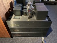
no it is all single ended. I did play with the idea, but balanced in tubes is a lot of extra stuff (and money)...
so what you see is my consistent signal interlinking with keeping the hot and cold signal inside a shielding. The shielding does not carry signal. So basically the audio GND is one of the two signal carriers inside the cable, which is pure silver core inside Teflon tube
This is done most practical with XLR connectors.
The circuits are all on my blog / website
but also below:
PS: yes the Tube is a special version with extra Power capabilities and sounds awsome (but extremely expensive unfortunately - hope they will be very long life
)The top enclosure with the two speakers units (the mid and tweeter unit) is filtered passively by a 12dB serial filter. (Driven by the B300 amp)
:
Attachments
Last edited:
I created a YouTube video of my complete Streamer with LCD display in a Beautiful Case. It can help give some people ideas as there is hardly any videos about this .
here is the link:
Amazing audiophile DIY music streamer for a dac, and how to build your own - YouTube
here is the link:
Amazing audiophile DIY music streamer for a dac, and how to build your own - YouTube
Last edited:
Final clock Tests?
It seems I am coming to an end with the clock listening tests
Although…. Not tried the “Ian-Oven” yet
I will definitively write a more comprehensive story on my blog site, but I will be traveling till Sunday, so I wanted to not let you all wait!
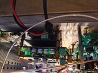
In the pictures you see that also finally my whole clock scheme is ready with the two best available clocks from Andrea (5.6 and 6.1 MHz) and the corresponding 4 doublers. So now I will be able to play all tracks up to 192kHz (That is also all I have)
I already reported on the difference between the sine to square converters so this time it is the following:
- SinePi with full Andrea Clock setup
- Neutron 3 11MHz with direct DIL connector (The Neutron outputs cmos square wave)
Both are powered by the Poor mans A123 / Ultracap power supply
Rest of the man cave is also known by now I presume…
Listening impressions:
Neutron comes very close to the Andrea Clocks, both on 44kHz as well 88kHz tracks.
But still the Andrea setup gives that extra spatial information and (I still wonder why) deepest bass impulses sound a little punchier (?) Again small, need to go back and forward several times, but it stays evident.
I also tried listening to a 192kHz track from LINN recordings and as only difference I switched off the power of the 5-11 doubler, so at the SinePi only the (Andrea) 24MHz clock signal arrived. I wanted to know if the fact, that the clock signals are being switched by only one relay could have an influence. Honest? Only pistol on the breast I say, yes it makes a minimal difference. But even so, my motto is always, what I prefer stays. So, I will feed the SinePi with only one clock signal. But please try this for yourself if it makes sense for you personally (Super surfer, pls also try?)
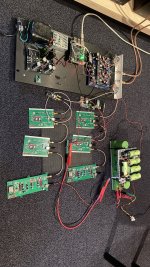
No, you wonder how this will be solved? Well I was already working on a separate chassis for the clocks where I wanted to get the max out of the base master clocks by the following setup:
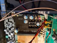
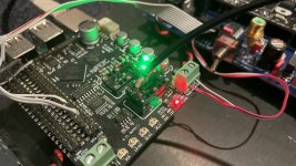
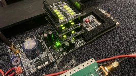
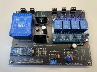
Control unit with Arduino (See picture = ready and works fine) doing the following:
Charger control. If voltage drops below 15,5 Volt the charger will be connected to charge the bank for 3 hours and charge till 16.8 Volt. When by coincidence, listening takes place and you do not want the charger to be connected, there is an override switch.
The unit will output digital control signals to go to a switch board where the clocks and doublers are connected (PCB is in design – 4 layers and RF relays) – The idea is that depending on FS (44.1, 48.0, 88.2 etc. etc.) only one clock with one or two doublers will be switched in to the right configuration and will output one sine wave clock signal going to the DAC Chassis with the SinePi
FS will be read directly from the Raspberry PI GPIO L/R clock. Also, front panel switches will allow for a manual override and manual selection of the cloak and how many doublers
All signals are connected by Optocouplers so there is full isolation between RPI, Clocks switch board and power supplies
So, when playing a 44.1 track the doublers are NOT switched in series after the master clock
I will blog later about the developments of course
Till then, great work Ian, thanks for the time and energy you have put in the SinePi (Oven still pending…)
Doede
.
It seems I am coming to an end with the clock listening tests
Although…. Not tried the “Ian-Oven” yet
I will definitively write a more comprehensive story on my blog site, but I will be traveling till Sunday, so I wanted to not let you all wait!
In the pictures you see that also finally my whole clock scheme is ready with the two best available clocks from Andrea (5.6 and 6.1 MHz) and the corresponding 4 doublers. So now I will be able to play all tracks up to 192kHz (That is also all I have)
I already reported on the difference between the sine to square converters so this time it is the following:
- SinePi with full Andrea Clock setup
- Neutron 3 11MHz with direct DIL connector (The Neutron outputs cmos square wave)
Both are powered by the Poor mans A123 / Ultracap power supply
Rest of the man cave is also known by now I presume…
Listening impressions:
Neutron comes very close to the Andrea Clocks, both on 44kHz as well 88kHz tracks.
But still the Andrea setup gives that extra spatial information and (I still wonder why) deepest bass impulses sound a little punchier (?) Again small, need to go back and forward several times, but it stays evident.
I also tried listening to a 192kHz track from LINN recordings and as only difference I switched off the power of the 5-11 doubler, so at the SinePi only the (Andrea) 24MHz clock signal arrived. I wanted to know if the fact, that the clock signals are being switched by only one relay could have an influence. Honest? Only pistol on the breast I say, yes it makes a minimal difference. But even so, my motto is always, what I prefer stays. So, I will feed the SinePi with only one clock signal. But please try this for yourself if it makes sense for you personally (Super surfer, pls also try?)
No, you wonder how this will be solved? Well I was already working on a separate chassis for the clocks where I wanted to get the max out of the base master clocks by the following setup:
Control unit with Arduino (See picture = ready and works fine) doing the following:
Charger control. If voltage drops below 15,5 Volt the charger will be connected to charge the bank for 3 hours and charge till 16.8 Volt. When by coincidence, listening takes place and you do not want the charger to be connected, there is an override switch.
The unit will output digital control signals to go to a switch board where the clocks and doublers are connected (PCB is in design – 4 layers and RF relays) – The idea is that depending on FS (44.1, 48.0, 88.2 etc. etc.) only one clock with one or two doublers will be switched in to the right configuration and will output one sine wave clock signal going to the DAC Chassis with the SinePi
FS will be read directly from the Raspberry PI GPIO L/R clock. Also, front panel switches will allow for a manual override and manual selection of the cloak and how many doublers
All signals are connected by Optocouplers so there is full isolation between RPI, Clocks switch board and power supplies
So, when playing a 44.1 track the doublers are NOT switched in series after the master clock
I will blog later about the developments of course
Till then, great work Ian, thanks for the time and energy you have put in the SinePi (Oven still pending…)
Doede
.
Attachments
It seems I am coming to an end with the clock listening tests
Although…. Not tried the “Ian-Oven” yet
I will definitively write a more comprehensive story on my blog site, but I will be traveling till Sunday, so I wanted to not let you all wait!
In the pictures you see that also finally my whole clock scheme is ready with the two best available clocks from Andrea (5.6 and 6.1 MHz) and the corresponding 4 doublers. So now I will be able to play all tracks up to 192kHz (That is also all I have)
I already reported on the difference between the sine to square converters so this time it is the following:
- SinePi with full Andrea Clock setup
- Neutron 3 11MHz with direct DIL connector (The Neutron outputs cmos square wave)
Both are powered by the Poor mans A123 / Ultracap power supply
Rest of the man cave is also known by now I presume…
Listening impressions:
Neutron comes very close to the Andrea Clocks, both on 44kHz as well 88kHz tracks.
But still the Andrea setup gives that extra spatial information and (I still wonder why) deepest bass impulses sound a little punchier (?) Again small, need to go back and forward several times, but it stays evident.
I also tried listening to a 192kHz track from LINN recordings and as only difference I switched off the power of the 5-11 doubler, so at the SinePi only the (Andrea) 24MHz clock signal arrived. I wanted to know if the fact, that the clock signals are being switched by only one relay could have an influence. Honest? Only pistol on the breast I say, yes it makes a minimal difference. But even so, my motto is always, what I prefer stays. So, I will feed the SinePi with only one clock signal. But please try this for yourself if it makes sense for you personally (Super surfer, pls also try?)
No, you wonder how this will be solved? Well I was already working on a separate chassis for the clocks where I wanted to get the max out of the base master clocks by the following setup:
Control unit with Arduino (See picture = ready and works fine) doing the following:
Charger control. If voltage drops below 15,5 Volt the charger will be connected to charge the bank for 3 hours and charge till 16.8 Volt. When by coincidence, listening takes place and you do not want the charger to be connected, there is an override switch.
The unit will output digital control signals to go to a switch board where the clocks and doublers are connected (PCB is in design – 4 layers and RF relays) – The idea is that depending on FS (44.1, 48.0, 88.2 etc. etc.) only one clock with one or two doublers will be switched in to the right configuration and will output one sine wave clock signal going to the DAC Chassis with the SinePi
FS will be read directly from the Raspberry PI GPIO L/R clock. Also, front panel switches will allow for a manual override and manual selection of the cloak and how many doublers
All signals are connected by Optocouplers so there is full isolation between RPI, Clocks switch board and power supplies
So, when playing a 44.1 track the doublers are NOT switched in series after the master clock
I will blog later about the developments of course
Till then, great work Ian, thanks for the time and energy you have put in the SinePi (Oven still pending…)
Doede
.
@Doede
Great implement, thank for sharing.
Regarding the NeutronStar, my experience was similar. In my system, NeutronStar (45.xxx MHz) has better 3D image focusing, but DRIXO (22.xxx MHz) plays more musical and has better bass. So over all, I still prefer DRIXO.
What's the power supply stacks on top of your NeutronStar? I don't have them in my setup. BTW, NeutronStar's sine output was not perfect, you have to remove the diode to eliminate the non-linearity level shift (please find my old post). And I suspect it's not SC-CUT crystal because the oven temperature was far from 80 degree.
Talking about the two frequencies interference, for RF signals, it's always there. Actually we can not eliminate it by 100%, we can only say it was reduced by how many dB. Because RF signal can be transmitted through air. Common mode interference would be one of the biggest issue so both ground and the signal have to be isolated for the un-selected clock. Theoretically three RF relays configuration could be a better solution I hope I can try it later once I have time.
Based on my time jitter measurement, the following steps can also be a great help to reduce the interference.
1. Separate the power supplies for different clock oscillators (don't share). This step can reduce the interference coupled by power rail. Indeed, for a ultra low phase noise application, power supply coupled interference really can not be ignored.
2. Separate the oscillators by more than three inches distance in between, even if they are inside metal cases.
Just hope you can try the oven solution and the 3000F ultracapacitor power supply soon, they really make a difference. I'm looking forward to your updates.
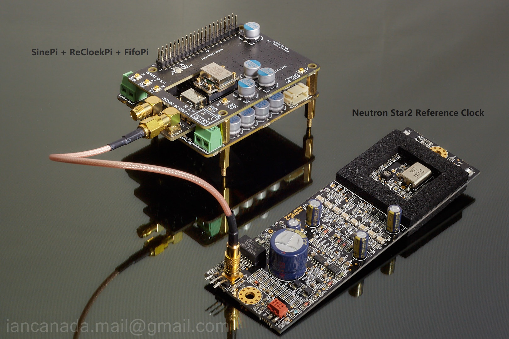
SinePi_NeutronStar2 by Ian, on Flickr
Regards,
Ian
Last edited:
I created a YouTube video of my complete Streamer with LCD display in a Beautiful Case. It can help give some people ideas as there is hardly any videos about this .
here is the link:
Amazing audiophile DIY music streamer for a dac, and how to build your own - YouTube
Sebbyp, Wlowes, Thank you
Doede, Thanks, I am still learning about the new clocks seems to change a lot over time, I am sure the upgrade bug will push for a change.
I am really enjoying your Blog and learning a lot. I see we share a PR99 Reel to reel hope you still like it.
-------------------------------------
See my Youtube Chanel

Thank you Ian and those that are sharing their experiences with the SinePi. That FiFoPi Q3 + SinePi + ReClockPi stack just looks so sweet.
My Mouser order shipped early, so the DIY wheels may start spinning again.
Maybe in a year, we can get a Group Buy of MagicXtal clocks in this shootout.
There's a reseller in Germany, but the MOQ is still 5. I can't confirm if they sell at:
Standard Frequencies: 11.289600 MHz 12.288000 MHz 22.579200 MHz 24.576000 MHz
45.158400 MHz 49.152000 MHz 90.316800 MHz 98.304000 MHz 100.000000 MHz
But at least it potentially avoids buying direct from Russia (Literally and Figuratively Red Tape). Plus potential miscommunication.
Axtal
Last edited:
Sebbyp, Wlowes, Thank you
Doede, Thanks, I am still learning about the new clocks seems to change a lot over time, I am sure the upgrade bug will push for a change.
I am really enjoying your Blog and learning a lot. I see we share a PR99 Reel to reel hope you still like it.
-------------------------------------
See my Youtube Chanel
Thanks for the flowers Gabster ! Oh, yes I saw yours as well in the video ! My PR99 was coming directly from the service department from Revox. Totally rebuild with NOS parts - A beauty.. a shame master tapes are so expensive LOL
@Doede
Great implement, thank for sharing.
What's the power supply stacks on top of your NeutronStar? I don't have them in my setup. BTW, NeutronStar's sine output was not perfect, you have to remove the diode to eliminate the non-linearity level shift (please find my old post). And I suspect it's not SC-CUT crystal because the oven temperature was far from 80 degree.
https://flic.kr/p/2m9wrNd
SinePi_NeutronStar2 by Ian, on Flickr
Regards,
Ian
Thanks Ian for more ideas. I was hoping when the two clocks are only connected directly ate the Ultracap output, the extreme low output impedance would dampen any connections sufficiently.... we will see, easy to experiment !
The stack is an extra noise filter for the onboard oscillator power supply. it can be stacked in parallel. It is offered in the web shop when you select the Neutron 3 clock.
It does a small extra for the clock and the cost is relative low (30 or 40 Euro I believe)
On the 3 I could not see any option to get a sine wave out of it. And I did not wanted to demolish the board as it is not mine....
- Home
- Source & Line
- Digital Line Level
- Asynchronous I2S FIFO project, an ultimate weapon to fight the jitter