What I do when using ASIO drivers is make sure a second sound device (dac) is connected to the PC, then assign it to be default communication device and default sound device. So long as Windows doesn't automatically change it back at some point, ASIO is not resampled. I also leave the Windows volume control for the device set to maximum. Don't know if Windows will try to change the volume level otherwise.
Windows is a general use OS and it makes sense that its default audio path mixes streams (hence resampling), changes volume, avoids clipping by compression etc. Just like pulseaudio in linux does.
But the wasapi exclusive mode is very similar to ASIO, I would say a direct replacement. Also it's very similar to alsa in linux in the PCM stream features. I think the much younger Wasapi has learned from alsa, it even shares some terminology. Wasapi offers (like asio and alsa) the very efficient callback mode (at DMA period boundary reported by the soundcard, to refill/read the previously consumed/refilled buffer), it's up to the application programmer if he wants to use it.
For testing the uac2 windows driver I am using the example in Henrik's (author of CamillaDSP) WASAPI crate in Rust wasapi-rs/playsine_events.rs at master * HEnquist/wasapi-rs * GitHub . Installing Rust via its cargo tool and compiling the example is trivial in windows, the cargo downloads all libraries and takes care of everything, just a single command. The example generates and plays in exclusive mode via the callbacks any sine signal at any samplerate and sample size which is all I need for the tests.
No need to rely on some black-box playback applications. E.g. Foobar2000 + its wasapi exclusive plugin do not play 32bit wavs bitperfectly (probably due to foobar's internal processing in float32). Henrik's example + WASAPI exclusive + Win10 UAC2 driver -> RPi4 async USB audio gadget are a bitperfect combination down to 32bits up to total USB2 isochronous bandwidth of some 8Mbytes/s (1024bytes x 8000 uframes per second).
Can someone help me follow how this discussion relates to this thread?
It is loosely related. If you are not interested, or don't understand, what's discussed here, you could just skip the messages. Not everything needs to be about the SQ effect of the sand filling the clock box.
I found it interesting early on. I stopped using Windows, USB, Foobar and ASIO years ago. I found the transition to a SBC running Linux into a reclocker/isolator far easier to produce the level of sound quality I seek. That is what led me to Ian's FIFO, the subject of this thread.
One could argue that people that do not find a need for FIFO need not comment?
One could argue that people that do not find a need for FIFO need not comment?
Last edited:
even the stock windows UAC2 driver seems to behave nice if the usb device respects its requirements
That's questionable and a big "if".
A big "if" indeed. Just a few weeks ago I was testing my STM32F7 UAC2 device against the stock Windows UAC2 driver (usbaudio2.sys). I had a typo in one of the interface descriptors. This caused an instant BSOD of the Windows host after enumeration. No events in any logs nor any memory dumps so close to impossible to debug. Brilliant software engineering by Microsoft. Luckily I had another XMOS based USB-to-I2S bridge (commercial) which I could use to compare the event logs usbaudio2 produces. This helped me to locate the typo.
I was testing my STM32F7 UAC2 device
Ahem... I suppose that's not an open source project, right?

bohrok2610: Thanks for sharing your experience. I am by no means saying the driver is flawless. In fact it took several years to make the linux audio gadget enumerate and work properly under this driver, while the linux uac2 driver has supported it for a long time. It's extremely picky about the USB config, about format of the async feedback value, about max packet sizes, etc.
On the other hand, when the USB device complies with all the strict peculiarities, the driver + wasapi exclusive API behave surprisingly flexible and performant, much better than I expected (such as supporting any samplerate the device reports, not just some hard-coded set of values, 32bits, etc).
I am talking about it here because IMO the very first step ań audio project should do is to try to have only one clock domain - the DAC master clock, by using communication means which are controlled by the sink clock (i.e. async USB, slaving I2S controllers). Only when this option is not technically available (i.e. having to support SPDIF input or some dumb streaming), should it look at multiple clock "brokers". Of which ASRC is the professional reliable solution with unavoidably higher jitter (no ASRC can reject the incoming clock jitter completely), and FIFO is the "works great but for a limited time and with large latency" solution.
There are a number of RPI-based great projects on this website which use FIFOs with great quality clocks which could relatively easily be redesigned to slave the RPi PCM interface (quite performant by itself) and avoid the jittery RPi clock generator (which has to use the limpy fractional divider due to shortage of clock PLLs in the RPi4 SoC) and the subsequent FIFO "broker" completely. Actually it's a pitty and surprising that no proper I2C-controlled clock hat for proper use of the I2S controller (+ the galvanic isolation to avoid ground loops e.g. with USB hosts) is being available, despite the many various "workarounds".
Last edited:
phofman, do we not have what you advocate with Ian's FIFOPi?
In my use case I run a simple TDA1541a DAC pcb from FIFOPi. There is only one clock domain that counts. The FIFOPi clock.
The data is buffered in FIFOPi. It is galvanically isolated from everything upstream. The DAC only sees data from FIFOPi clocked by the clock that is installed to FIFOPi. That clock is the master clock. There is no other.
Sure there is a clock in the Rpi. Another in the SBC that acts as router. Another in the SBC that runs the NAS and still another in the Android phone that runs the man machine interface to MPD. But none of those have anything to do with playback. Actual playback is FIFOPi driving the DAC chip.
Right?
Perhaps Ian can set me straight if I am missing something.
wlowes: what clocks the incoming data into the fifo? Most likely your I2S is running in master mode, using PLLed clock from the 27/54MHz RPi crystal and divided by the fractional MASH divider. This clock determines the playback rate as it controls the player software. This clock differs from your DAC clock, and the fifo will under/overflow, eventually. It may take a very long time, depending on the FIFO length. The larger "headroom" the fifo makes, the longer the latency before it's filled enough to start playback. Or some clever hacks are programmed in the fifo board, to avoid the stall, such as dropping or duplicating samples.
In your case the DAC bitclock (which incidentally is TDA's master clock too as the TDA is a 16bit parallel NOS DAC, IIRC) could feed the RPi I2S slaved bitclock input and the DAC bitclock input at the same time, and RPi could do the /16 division to the frame clock itself (bit clock slave, frame clock master). No need to merge the two clock domains by the FIFO. That would be the technically correct solution, IMO.
But I understand that using a ready-made board with FIFO and galvanic isolation, using some of the existing drivers for the RPi DACs is practically way easier, especially when no clock-fanout board with galvanic isolation exists. Makes perfect sense.
"wlowes: what clocks the incoming data into the fifo? "
It does not matter. It is buffered in FIFO. Matters no more than the timing the data spent on the CD before I ripped to the NAS. Those times are irrelevant to playback sound quality. What matters is the timing when the data is converted to sound in the bowels of the TDA1541a. That is determined by FIFO, the clock FIFO uses, the transmission line FIFO to DAC and the noise everywhere around those components that can add jitter. Ground plane noise, signal attenuators, path length all count. Clocks upstream to the FIFO buffer do not have an impact other than any noise they generate that creeps into the stuff that does count.
"But I understand that using a ready-made board with FIFO and galvanic isolation, using some of the existing drivers for the RPi DACs is practically way easier, especially when no clock-fanout board with galvanic isolation exists. Makes perfect sense."
That is why I use it. I started my digital experiment with windows driving a USB DAC. We had to build special purpose PC's, carve WINXP down to a barely bootable single purpose kernal, fight a never ending battle with USB... It worked, but it was exhausting. Now with a good FIFO, an exceptional clock and some crazy attention to power supplies, we get it all with reasonable reliability.
It takes more than a little sand to make good sound. from digital. Everything matters. But you can go a long way with some well thought out building blocks.
wlowes: what clocks the incoming data into the fifo? Most likely your I2S is running in master mode, using PLLed clock from the 27/54MHz RPi crystal and divided by the fractional MASH divider. This clock determines the playback rate as it controls the player software. This clock differs from your DAC clock, and the fifo will under/overflow, eventually. It may take a very long time, depending on the FIFO length. The larger "headroom" the fifo makes, the longer the latency before it's filled enough to start playback. Or some clever hacks are programmed in the fifo board, to avoid the stall, such as dropping or duplicating samples.
In your case the DAC bitclock (which incidentally is TDA's master clock too as the TDA is a 16bit parallel NOS DAC, IIRC) could feed the RPi I2S slaved bitclock input and the DAC bitclock input at the same time, and RPi could do the /16 division to the frame clock itself (bit clock slave, frame clock master). No need to merge the two clock domains by the FIFO. That would be the technically correct solution, IMO.
But I understand that using a ready-made board with FIFO and galvanic isolation, using some of the existing drivers for the RPi DACs is practically way easier, especially when no clock-fanout board with galvanic isolation exists. Makes perfect sense.
Bitclock does not matter much with the TDA1541A, using it in simoultaneous mode the most crucial timing signal is the latch enable which drives the DAC switches.
The only purpose of the bitclock is loading the registers of the DAC and you could easily stop it before latching to avoid interference with the LE.
So I would avoid using the RPI to do the division in order to generate the latch enable, I would avoid the LE to cross other devices at all.
The best way is generating the LE directly from the master clock, fully isolated from bitclock and data.
Optically isolated if possible.
It's not a great issue avoiding to get the FIFO buffer under/overflow, simply adjust the FIFO during music pauses.
"wlowes: what clocks the incoming data into the fifo? "
It does not matter. It is buffered in FIFO.
It does not matter from the sound quality POW, but from the frequency difference which causes the FIFO to under/overflow eventually. Unless some "hacks" are used to prevent that which by principle cannot be 100% reliable (but most likely perfectly adequate for consumer audio).
Anyway, good that you are satisfied with your setup.
So I would avoid using the RPI to do the division in order to generate the latch enable, I would avoid the LE to cross other devices at all.
Sure, that's why I was talking about a clock distribution shield. Moreover, most people use oversampling DACs with master clock, apart of the bitclock and frame clock of I2S. They all could be generated by the clock shield, slaving the I2S controller completely.
It's not a great issue avoiding to get the FIFO buffer under/overflow, simply adjust the FIFO during music pauses.
Yes for music playback, hardly e.g. for measurements - your long-time jitter phase measurements or collecting averaged 1M FFTs would not like the added/removed samples
Also professional audio needs long-term recording sessions which cannot rely on music pauses to recover the fifo fill level. That's why professional audio solutions use the ASRC instead of fifos (and measurements use single clock domain only).But again - perfectly adequate for consumer audio.
Last edited:
The Ian first fifo was dimensioned so that one could play a whole CD within the corners of the s/pdif spec - this means something like 1/2 a second wait for the first tone of Beethoven's 9:th In my normal 1 DAC stereo music system I did not mind. Now, with 2 way stereo with one DAC per Way, its unusable...
//
In my normal 1 DAC stereo music system I did not mind. Now, with 2 way stereo with one DAC per Way, its unusable...//
Sure, that's why I was talking about a clock distribution shield. Moreover, most people use oversampling DACs with master clock, apart of the bitclock and frame clock of I2S. They all could be generated by the clock shield, slaving the I2S controller completely.
Yes for music playback, hardly e.g. for measurements - your long-time jitter phase measurements or collecting averaged 1M FFTs would not like the added/removed samples
But again - perfectly adequate for consumer audio.
Measurements and professional audio are different things, I was talking about the TDA1541A implementation.
Anyway, for consumer audio, with a well implemented (well isolated) FIFO buffer you can clean up the jitter of whatever I2S source you want, while slaving the I2S source is not always possible.
Nothing to do with the part but the implementation is flawed. I'll be interested to see what you get.
After thinking about it for a while.
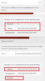
I believe the alleged glitch issue could come from the two's complement DAC implementation.
At zero crossing all the switches of the DAC change theirs state (eg. from 00000000000000000000 to 11111111111111111111), this could cause the glitch.
I wonder why your former fellows have not implemented the sign magnitude DAC operation which could solve the glitch issue.
Maybe I'm wrong, but seems like a pride issue.
Since BB (TI) implemented it before us then we can't follow this way because we wouldn't be the first to do it.
Pride aside, I believe the best way to solve the alleged issue is to get the AD5791 to work as a sign magnitude DAC.
This means that a couple of DAC have to be used for each channel, for a total of 4 DACs to get a stereo device.
This way all the switches of the DACs never change their state at the same time because the first DAC will cover the positive rail and the second DAC the negative one.
In other words the MSB of each DAC will operate as the sign, so for the first DAC the MSB always is set to 0 and for the second DAC the MSB always is set to 1.
This way needs a custom driver for the DAC and a voltage summing amplifier at the output of the two DACs
Of course this will be a little expensive.
Attachments
- Home
- Source & Line
- Digital Line Level
- Asynchronous I2S FIFO project, an ultimate weapon to fight the jitter