Can a Chord Dac be slaved ? I'm not sure ! And it's fgpa inside which is oversampling at max !
No, it's pretty much a non-DIY consumer DAC. The signal is re-clocked via software code internally within the FPGA.
Although you can max oversample, I prefer to keep is simple and stick with redbook.
I use to be Hirez only, but Chord DACs opened my ears to what redbook can produce. This only happened after I switched to a Music Streamer and optical so I consider the Music Streamer important in the chain. That's why I'm focusing on how to max out a DIY Squeezebox Music Streamer. It may or may not work out, but worth a shot.
Last edited:
Does anyone know if GPIO 4 is free on a FiFoPi / TransportPi setup?
I use that for a IR Receiver w/ emulated IR Squeezebox Remote for my current build.
I prefer a IR Remote versus using a Smartphone as it is more responsive and has an old school feel to the music experience.
I use that for a IR Receiver w/ emulated IR Squeezebox Remote for my current build.
I prefer a IR Remote versus using a Smartphone as it is more responsive and has an old school feel to the music experience.
That's funny, cause I believed the Chord Dacs was oversampling anything before dac conversion showing at least something 776 Mhz ?!
So you can make a difference wit what you feed it. That's interesting. I believe some old Red Book were good cause at the beginning they were coming from analog tapes. I'm asking myself if we didn't like some cd after when they went to record with some adc which were not as good than the ones they had for converting the analog tapes directly when there was this sugden change from LPs to CDs ???
I am a very Red-Book too and still use as main a 16 bits dac chip non oversampled -though not sure the oversampling is the problem : the digital reccording perhaps !-
As the designer suggested ("If you are interested in, I'd be glad to discuss with you the FifoPi principle in my thread.") I move the discussion around the FifoPi here, I agree this thread is more appropriate for the topic.
Please, let me remind that I still wait for the analog view of the LRCK after FifoPi with the time division set to 50 ns.
And also it could be useful to see the waveform of the LRCK before the D-FF.
I report here the last post from the other thread, this should be a good starting point to understand the "FifoPi principle".
About spurs and integration bandwidth I suggest a full immersion in the literature you can find at Rubiola.org.
So you will understand the meaning of the power supply spurs and mostly what you have to care about the phase noise at 6 MHz from the carrier (half the carrier frequency).
Moreover you can play with a phase noise to jitter converter to understand that the major contribution to the jitter calculation comes from the close in phase noise and not at 6 MHz from the carrier (that weights nothing).
But as I have already pointed out, if your goal is to remove the spurs from the power supply of the Rpi then you have reached the target.
We have all understood that your real time digital oscilloscope is the reference gear to measure the jitter, so keep out for a while the RPi measurements and focus to the FifoPi SCK and master clock (Crystek) measurements.
Your FifoPi operates in a different domain then we have to assume that it was not source dependent, so the source is not relevant in the investigation.
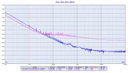
I attach again the phase noise plot of the FIfoPi SCK vs the master clock.
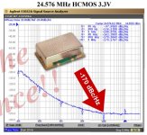
I also attach the phase noise plot of the Crystek CCHD-957 at 24.576 MHz, measured from the manufacturer using an Agilent E5052A (it uses cross correlation to measure the phase noise like the Timepod).
As you can see the phase noise plots are almost equal, the measurement from the Timepod is around 2 dB better against the E5052A. You should know that could be a difference from a crystal to another, mostly if we are talking about cheap crystal. Maybe we have got one of the best.
This means that the measurement from the Timepod is reliable, at least at 24.576 MHz.
Since the half frequency of the master clock (12.288 MHz) is still in the range of the Timepod we can assume the reliability of the FifoPi SCK phase noise measurement.
Now the jitter, as you can see the calculated jitter from the Timepod is almost the same from your digital oscilloscope, a little less than 3 ps.
We have to assume the reliability of the calculation.
A little digression, take a look at this link Crystek CCHD-957 | H i F i D U I N O
They have calculated the jitter with a different integration bandwidth, so the Crystek is more than one order of magnitude better, 120 fs!
What a trick!
This says a lot about the usefulness of the jitter measurement.
But if you take a look at the phase jitter per segment you see that the major contribution is in the 10 Hz region (1 Hz is missing), so you can understand the possible weight of the 6 MHz from the carrier you are pointing out, null.
Back to the topic, I forward again a few simple questions, just in cause you would kindly answer:
- the phase noise measurements of the Crystek are almost identical (Timepod vs E5052A), can you trust the measurement?
- the calculated jitter is identical, can you trust the measurement?
- what does 3 ps jitter explains?
- is 3 ps of jitter the "ultimate" performance to be reached?
- why the phase noise grows above 10 Hz from the carrier?
Please, let us know.
P.S.
Dividing the master clock you should get 6 dB better phase noise. Sometimes the real world confirms the theoretical laws, from 1 Hz to 10 Hz from the carrier the phase noise of the SCK (the master clock divided by 2) is effectively 6 dB better.
So the SCK output of the FifoPi, after removing the noise from the RPi, is improved by 6 dB against the master clock. Good news for the 1704 and 1794 users.
Please, let me remind that I still wait for the analog view of the LRCK after FifoPi with the time division set to 50 ns.
And also it could be useful to see the waveform of the LRCK before the D-FF.
I report here the last post from the other thread, this should be a good starting point to understand the "FifoPi principle".
About spurs and integration bandwidth I suggest a full immersion in the literature you can find at Rubiola.org.
So you will understand the meaning of the power supply spurs and mostly what you have to care about the phase noise at 6 MHz from the carrier (half the carrier frequency).
Moreover you can play with a phase noise to jitter converter to understand that the major contribution to the jitter calculation comes from the close in phase noise and not at 6 MHz from the carrier (that weights nothing).
But as I have already pointed out, if your goal is to remove the spurs from the power supply of the Rpi then you have reached the target.
We have all understood that your real time digital oscilloscope is the reference gear to measure the jitter, so keep out for a while the RPi measurements and focus to the FifoPi SCK and master clock (Crystek) measurements.
Your FifoPi operates in a different domain then we have to assume that it was not source dependent, so the source is not relevant in the investigation.
I attach again the phase noise plot of the FIfoPi SCK vs the master clock.
I also attach the phase noise plot of the Crystek CCHD-957 at 24.576 MHz, measured from the manufacturer using an Agilent E5052A (it uses cross correlation to measure the phase noise like the Timepod).
As you can see the phase noise plots are almost equal, the measurement from the Timepod is around 2 dB better against the E5052A. You should know that could be a difference from a crystal to another, mostly if we are talking about cheap crystal. Maybe we have got one of the best.
This means that the measurement from the Timepod is reliable, at least at 24.576 MHz.
Since the half frequency of the master clock (12.288 MHz) is still in the range of the Timepod we can assume the reliability of the FifoPi SCK phase noise measurement.
Now the jitter, as you can see the calculated jitter from the Timepod is almost the same from your digital oscilloscope, a little less than 3 ps.
We have to assume the reliability of the calculation.
A little digression, take a look at this link Crystek CCHD-957 | H i F i D U I N O
They have calculated the jitter with a different integration bandwidth, so the Crystek is more than one order of magnitude better, 120 fs!
What a trick!
This says a lot about the usefulness of the jitter measurement.
But if you take a look at the phase jitter per segment you see that the major contribution is in the 10 Hz region (1 Hz is missing), so you can understand the possible weight of the 6 MHz from the carrier you are pointing out, null.
Back to the topic, I forward again a few simple questions, just in cause you would kindly answer:
- the phase noise measurements of the Crystek are almost identical (Timepod vs E5052A), can you trust the measurement?
- the calculated jitter is identical, can you trust the measurement?
- what does 3 ps jitter explains?
- is 3 ps of jitter the "ultimate" performance to be reached?
- why the phase noise grows above 10 Hz from the carrier?
Please, let us know.
P.S.
Dividing the master clock you should get 6 dB better phase noise. Sometimes the real world confirms the theoretical laws, from 1 Hz to 10 Hz from the carrier the phase noise of the SCK (the master clock divided by 2) is effectively 6 dB better.
So the SCK output of the FifoPi, after removing the noise from the RPi, is improved by 6 dB against the master clock. Good news for the 1704 and 1794 users.
Attachments
Last edited:
That's funny, cause I believed the Chord Dacs was oversampling anything before dac conversion showing at least something 776 Mhz ?!
So you can make a difference wit what you feed it. That's interesting. I believe some old Red Book were good cause at the beginning they were coming from analog tapes. I'm asking myself if we didn't like some cd after when they went to record with some adc which were not as good than the ones they had for converting the analog tapes directly when there was this sugden change from LPs to CDs ???
I am a very Red-Book too and still use as main a 16 bits dac chip non oversampled -though not sure the oversampling is the problem : the digital reccording perhaps !-
I believe your thinking of a specific Chord product that upsamples and not necessarily the DAC:
The Hugo M Scaler is a highly advanced standalone upscaler capable of redefining sound quality from digital audio. It uses Rob Watts’ (our Digital Design Consultant’s) unique filter technology, the most advanced in the world, to upscale standard 44.1kHz digital audio up to 705.6kHz (16x CD’s 44.1kHz native resolution), ready to be passed to a suitable DAC; Hugo M Scaler extends its upscaling performance to 768kHz (from 96kHz input data) for our dual-BNC-input DACs.
Even with a Chord M Scaler, I would stick with redbook. Especially if your running a solo 5 MHz crystal. That seems like a highly-efficient optimal process.
I will get a better feel for differences once I put the Accusilicons (cross fingers) in the chain. The high-end streamers have clocks so they seem to make a difference. I could not listen without my first Music Streamer with basic clocks (WM8804) in the chain. In any case, feeding it the cleanest signal should not hurt. I'm after improved PrAT and squeezing out that extra 1-10% if possible.
I believe redbook has always been good depending on the mastering and all that is needed for sound reproduction. In my case, it needed a powerful FPGA and a genius DAC designer to get me back on board where it gets you to close to LIVE music as possible.
Speaking of ADC, Chord is working on a ADC called Davina. It will take at least a few more years to launch.
Anyways, enough Chord talk let's get this thread back on track...
Last edited:
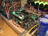
Due to the discussion between Ian and Andrea on the fifopi I have finally (I wanted to do this for a while now) put 2 fifopi’s in series to see if it will benefit the sound.
I will let it play for a while before writing my final judgement but the first impression is that it has an audible effect.
Is there anybody else that has tried this?
Regards,
I will let it play for a while before writing my final judgement but the first impression is that it has an audible effect.
Is there anybody else that has tried this?
Regards,
Attachments
Fascinating idea! Let us know your thoughts on sound if any.Due to the discussion between Ian and Andrea on the fifopi I have finally (I wanted to do this for a while now) put 2 fifopi’s in series to see if it will benefit the sound.
I will let it play for a while before writing my final judgement but the first impression is that it has an audible effect.
Is there anybody else that has tried this?
Regards,
Due to the discussion between Ian and Andrea on the fifopi I have finally (I wanted to do this for a while now) put 2 fifopi’s in series to see if it will benefit the sound.
I will let it play for a while before writing my final judgement but the first impression is that it has an audible effect.
Is there anybody else that has tried this?
Regards,
Very creative Stefan
")
I see Andrea clock on top, but what clock did you put in the pre-fifopi ? And what did you actually compare ? Top versus top-with-pre ?
Hi Doede,
For the 44.1khz family the bottom fifopi has a crystek clock and the top one the Andrea Mori driscoll with SC-cut crystal.
For the 48khz family bottom fifopi uses the standard supplied clock and the top one the crystek.
I want to compare the difference in sound with one or 2 fifopi’s.
The fifopi does not isolate the source for 100% (nor do the others I have used like Acko isolator/recklocker, twisted pear cronus/hermes and Allo Kali and isolator)
Changes in the source are audible, like changing the rpi for an usbridge and changing power supplies to these devices.
The bottom fifopi is powered with the shanti and UcConditioner on 5v (a new and unused one so it has to run in)
The top fifopi is battery and UcHybrid powered 3,3v (local regulator bypassed).
The Andrea Mori clock is battery/UcHybrid powered.
Supersurfer
Interesting. I did not know you could put Andre's WTMC in the 45 slot and a conventional clock in the 48. I just assumed there would be issues as the basic WTMC board does not use the clock selection pin and is running all the time. So I left the 48 side empty and just convert everything to redbook speed. Sounds like I could put my NDK SDA in the other slot and let FIFO select?
Interesting. I did not know you could put Andre's WTMC in the 45 slot and a conventional clock in the 48. I just assumed there would be issues as the basic WTMC board does not use the clock selection pin and is running all the time. So I left the 48 side empty and just convert everything to redbook speed. Sounds like I could put my NDK SDA in the other slot and let FIFO select?
Supersurfer
Interesting. I did not know you could put Andre's WTMC in the 45 slot and a conventional clock in the 48. I just assumed there would be issues as the basic WTMC board does not use the clock selection pin and is running all the time. So I left the 48 side empty and just convert everything to redbook speed. Sounds like I could put my NDK SDA in the other slot and let FIFO select?
I assume the clock positions are both powered constantly on the fifopi (Ian can you confirm?) turning clocks on and off between files is not optimal because they need to reach a steady state after a while powered.
Agreed. 99.9% of my listening is redbook, so 5Mhz WTMC for that. Then stuff my old 48Mhz NDK SDA in the other slot. Or possibly run the 1999 vintage Driscoll at 48Mhz for occasional HiRes/DSD and 5Mhz for the bulk of my listening. I have actually convinced myself that I prefer redbook speed on the NOS TDA1541a. Best yet is 176.4khz downsampled to 44.1khz.
The best advice I can give is to generate the LRCK dividing directly the master clock outside of the FPGA with separate VCC and ground.
With 5/6 MHz master clock you can play 176/192 kHz.
@andrea
I don't think dividing the MCLK by a digital counter logic is a good idea.
If you use an asynchronous counter, there will be much more jitter at output. If you use synchronous count, the principle will be as same as FifoPi because they are all flip-flops based, the finial output jitter will be MCLK jitter + additive jitter of the counter flip-flops. I didn't see any new advantages.
To use DDS or PLL based divider would be fine if you don't mind they are mainly designed for communication applications.
Analog RF clock divider could be another solution, but how to implement would be a question.
Regards,
Ian
Division homework for the obsessed: http://www.ke5fx.com/regen/1208.pdf
Notes on Low-Noise Regenerative Dividers
A good synchronous divider should avoid many of the issues of ripple counters etc. Some effort at the output to remove harmonics would help but you are planning a pure binary divider so it should be pretty free of spurs.
Notes on Low-Noise Regenerative Dividers
A good synchronous divider should avoid many of the issues of ripple counters etc. Some effort at the output to remove harmonics would help but you are planning a pure binary divider so it should be pretty free of spurs.
@andrea
I don't think dividing the MCLK by a digital counter logic is a good idea.
If you use an asynchronous counter, there will be much more jitter at output. If you use synchronous count, the principle will be as same as FifoPi because they are all flip-flops based, the finial output jitter will be MCLK jitter + additive jitter of the counter flip-flops. I didn't see any new advantages.
To use DDS or PLL based divider would be fine if you don't mind they are mainly designed for communication applications.
Analog RF clock divider could be another solution, but how to implement would be a question.
Regards,
Ian
Conversely I think so, anyway I would keep the dividers outside the FPGA slaving the FIFO to the divided clock.
And if you are looking at the best then use regenerative dividers as Demian has pointed out, that's what we are working on for the top version of our FIFO.
Obviously, if you want to stack the FIFO on the RPi you will never have enough space to do it.
I know that FPGA and software make the job easier and allow to save space, I work in IT, but sometimes source code and debug iterations are not enough.
@andrea,
Source jitter doesn't path through Fifo memory. FPGA jitter doesn't path through flip-flop. That's the principle.
I can not see using one or more counters as a frequency divider at finial stage has any chance to lower the output jitter of SCK and LRCK than flip-flops. And what is more is that it could introduce addition logic and frequency components to the finial output section which is what I don't want. However, if you insist, please go ahead. I don't think that's a big deal.
I'm glad you are working on the analog RF frequency divider similar to what Demian mentioned. I would say good luck to your project.
BTW, I could be wrong, but a FPGA should be slaved to the MCLK as what a FifoPi does. If a FPGA slaved to the divided clock, it will be no longer in the synchronous logic architecture which is believed having the best low jitter performance.
Regards,
Ian
Last edited:
- Home
- Source & Line
- Digital Line Level
- Asynchronous I2S FIFO project, an ultimate weapon to fight the jitter