Hi Ian, I'm trying to use the i2s back door input on my SPDIF board. When I cycle the input so that all three lights are lit, I get both the 'empty' and 'lock' lights come on. If I switch to the coax input it works fine - just the 'lock' status is shown. My I2S source is a Raspberry Pi 2. This works fine if I connect it directly to the buffer board.
Does this combination of lights mean I have gone wrong with my soldering of the four pin I2S connector on the SPDIF board? I have R22 connected to gnd on my Pi. Is there a way I can fault find using my multimeter?
Does this combination of lights mean I have gone wrong with my soldering of the four pin I2S connector on the SPDIF board? I have R22 connected to gnd on my Pi. Is there a way I can fault find using my multimeter?
Hi Ian, I'm trying to use the i2s back door input on my SPDIF board. When I cycle the input so that all three lights are lit, I get both the 'empty' and 'lock' lights come on. If I switch to the coax input it works fine - just the 'lock' status is shown. My I2S source is a Raspberry Pi 2. This works fine if I connect it directly to the buffer board.
Does this combination of lights mean I have gone wrong with my soldering of the four pin I2S connector on the SPDIF board? I have R22 connected to gnd on my Pi. Is there a way I can fault find using my multimeter?
I had this - it probably means that you've got the I2S connections muddled up but it's also worth checking whether you have the speed setting on the clock board set to fast instead of normal, depends on the speed of your clocks but it prob should be normal.
No lock above 96k bitrate (24bit) for PCM
I have been trying to resolve this problem for a while now with very little success and I’d appreciate anyone’s help in suggesting possible avenues of investigation. Why am I posting there rather than the Buffalo thread? It strikes me (possibly mistakenly!!) that as both DAC boards (I’m running dual mono) are responding in exactly the same way, the problem lies upstream of them – somewhere in the FIFO set up perhaps, or before, but I am running out of ideas for things to test.
When trying to play PCM, when I increase the bit rate beyond 96k I get no sound – literally no sound at all…not even an audible attempt to get a lock. At 176/192 the correct clock board LED lights and the FIFO lock light is green and solid. When I increase to 384k the lock LED on the FIFO board flickers regularly with the 128 LED on the clock board lit.
My DAC is setup as follows:
WaveIO (recently replaced with sonore I2S card with OSF built in) > Ian’s FIFO v2 with isolator and latest dual clock board running at normal speed (45/49 clocks) > dual mono Buffalo IIIse’s with internal MCLK disabled and fed from the clock board.
What I’ve done so far:
1) Tried various combinations of the relevant BIII DIP switches: DPLL settings (all now set to highest), OSF switch. Nothing appears to make any difference. So I assumed that something more fundamental is wrong.
2) Exchanged u.fl cables from usb card > FIFO card for 1.38mm diameter x 5cm – no change
3) I removed the FIFO boards from the DAC and replaced all the existing u.fl cables with new ones (decent quality 1.38mm x 10cm long) – no change
4) I removed the remaining ribbon cables I was using and soldered u.fl sockets in place. New u.fl cables used (same spec as above). u.fl now used throughout - no change
5) Tried the onboard 384k OSF in the sonore card in case there was some problem with the high bitrate stream coming from outside the DAC. The FIFO LEDs change appropriately but no change
6) Checked for voltage droop on BIII’s whilst attempting to play 384k – 5.25v at VDD and 3.3/1.2v at the reg outputs…looks good.
7) Tried an alternative USB to I2S card
Possible remaining problems that I can think of:
1) The 2 x MCLK u.fl cables are 2cm longer than the 6 x other u.fl cables – do the MCLK u.fl cables need to be the same length or is it just the other connections?
2) U.fl cables maybe too long? – this is going to be difficult to resolve due to PCB layout.
Things I can think of still to try - in increasing levels of pain to accomplish ;-):
1) Try Lifepo battery to power the clock board in case the regulator I’m using can’t supply required power (I’m stretching here because on my clock board the clocks are being powered externally so the board isn’t even having to power the clocks – current requirements must be minimal)
2) Revert to the internal BIIIse 100MHz clocks for MCLK duties
3) Bypass the FIFO circuit entirely and jump from USB card straight to one of the DACs to narrow down the problem
If anyone can spot that I’m missed anything in my problem solving I’d appreciate it pointed out. I have access to a frequency counter, scope and DMM.
Cheers
Crom
Hi Ian,
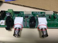
I am building the fifo reclocker and I found that there is no nuts included for the two BNC sockets. I measured it and found it is about 12mm diameter but I can't fit my 12mm diameter nut into it. Can you tell me what's the specification for those nuts? Thanks
I am building the fifo reclocker and I found that there is no nuts included for the two BNC sockets. I measured it and found it is about 12mm diameter but I can't fit my 12mm diameter nut into it. Can you tell me what's the specification for those nuts? Thanks
Attachments
Hi @iancanada,
I'm not sure if I can use your FIFO project for my application - hopefully you can direct me to the correct solution")
What I want to do is get the i2s output from my Raspberry Pi and turn that into an AES/EBU balanced digital connection for my Meridian speakers.
Do I need to have the FIFO main board, or do I just need the SPDIF board + a clock?
2nd question, which may or may not be related:
I'd like to get one digital and one analog input for my Raspberry Pi, what's the best way to do that? A usb interface like the Behringer U202? There are also cards like the Wolfson dac card, but I presume they would be mutually exclusive to your FIFO interface?
Thanks,
James
I'm not sure if I can use your FIFO project for my application - hopefully you can direct me to the correct solution
What I want to do is get the i2s output from my Raspberry Pi and turn that into an AES/EBU balanced digital connection for my Meridian speakers.
Do I need to have the FIFO main board, or do I just need the SPDIF board + a clock?
2nd question, which may or may not be related:
I'd like to get one digital and one analog input for my Raspberry Pi, what's the best way to do that? A usb interface like the Behringer U202? There are also cards like the Wolfson dac card, but I presume they would be mutually exclusive to your FIFO interface?
Thanks,
James
What I want to do is get the i2s output from my Raspberry Pi and turn that into an AES/EBU balanced digital connection for my Meridian speakers.
Do I need to have the FIFO main board, or do I just need the SPDIF board + a clock?
I know nothing about the FIFO, but if that turns out to be unsuitable you could look at the forthcoming Pi HAT from pi2design.com, which has AES/EBU.
Hi Ian,
I am building the fifo reclocker and I found that there is no nuts included for the two BNC sockets. I measured it and found it is about 12mm diameter but I can't fit my 12mm diameter nut into it. Can you tell me what's the specification for those nuts? Thanks
There is nothing special about these nuts. I took the nuts off from my old BNC connectors, and they just fit in.
That's true for most of us, I'm afraidThere is nothing special about these nuts.
Sorry, I couldn't help myself

BNC Nuts
Kenneth,
I believe the nuts are 1/2-28, which is an imperial fastener. Mouser p/n 523-31-5652. It is my suggestion, however, not to use a nut on the BNCs unless you are very careful with the mounting of the board itself. Using a nut on the BNC could have the tendency to torque the connector and stress the soldered pins unless the BNC, the board, and the panel are nearly perfectly aligned. If you just connect a cable to the BNC once (or twice, i.e., not every day), there is not a need to fasten the BNC to the panel.
George
There is nothing special about these nuts. I took the nuts off from my old BNC connectors, and they just fit in.
Thanks. I bought the nuts required.
Also thanks George for your tips.
Hi all,
I have done the wiring and mounted the four cards (fifo, isolator, reclocker, spdif). I connect spdif to fifo I2S #1, fifo i2s out to isolator, isolator to reclocker, reclocker i2s out J3 to spdif J8 plus MCLK cable between.
I power up them (only fifo and the reclocker), seems ok.
I use Squeezebox Receiver I2S as source and connect to I2S input #2 of fifo. The lock led lit and the reclocker shows 1024fs. When I play 44.1 music from Squeezebox, the coaxial output shows 88k. I also played 96k music and it doesn't output the rate correctly.
Then I plug a coaxial of 48k signal and select I2S #1 in fifo. Now it shows 1024fs and coaxial output shows 176k. In both cases, no music is outputted finally.
Is there anything I missed / doing wrong? Thanks a lot.
I have one more question, regarding the spdif card, there's a power supply input of 5V, the manual said it should be skipped if connected with fifo card. So it means the spdif card shares the same PS as the fifo card? I suppose the spdif card contains two parts, the DIR and the DIT part. It's okay for DIR part to share PS with fifo card but for DIT it should be powered by the reclocker card, right? Is it possible to change the wiring so that it is powered by two different PS?
Thx
Thx
When trying to play PCM, when I increase the bit rate beyond 96k I get no sound – literally no sound at all…not even an audible attempt to get a lock. At 176/192 the correct clock board LED lights and the FIFO lock light is green and solid. When I increase to 384k the lock LED on the FIFO board flickers regularly with the 128 LED on the clock board lit.
I have now resolved the problem. For anyone else in similar situation, my resolution was to increase the available current to the clock board!
Hi Jojip,
It works with any multi-channel/stereo I2S/DSD source. It will work with MiniSHARC DSP.
MC FIFO achieved by pure FPGA hardware. Software is just for control,diaplay and settings.
Regards,
Ian
Hi Ian,
I am new member and very interested in your FIFO reclocker Since I don't need SPDIF input, which make SPDIF interface board a bit redundant, so I want to ask a small question: Can I use some cheap i2s-spdif interface like hifiberry Digi+ instead of your SPDIF interface board to work with FIFO reclocker and clock board.
Regards,
Mai
I'm afraid not. I've also researched this topic awhile ago. DIT portion needs to be software programmed (SPI interface) that is why there is a link between FIFO and DIT.I have one more question, regarding the spdif card, there's a power supply input of 5V, the manual said it should be skipped if connected with fifo card. So it means the spdif card shares the same PS as the fifo card? I suppose the spdif card contains two parts, the DIR and the DIT part. It's okay for DIR part to share PS with fifo card but for DIT it should be powered by the reclocker card, right? Is it possible to change the wiring so that it is powered by two different PS?
Thx
Mounting holes and ground
Hi, could someone tell me if mounting holes on fifo, isolator, clock board, i2s-to-pcm and spdif boards are connected to ground?
I plan to mount boards on an aluminium sheet and I am not sure if I should use brass or nylon standoffs.
Looking at pictures of how Ian stacked the boards (fifo+isolator+clock) all with metal standoffs, suggests there is no ground connection between them, correct?
Thanks!
I have one more question, regarding the spdif card, there's a power supply input of 5V, the manual said it should be skipped if connected with fifo card. So it means the spdif card shares the same PS as the fifo card? I suppose the spdif card contains two parts, the DIR and the DIT part. It's okay for DIR part to share PS with fifo card but for DIT it should be powered by the reclocker card, right? Is it possible to change the wiring so that it is powered by two different PS?
Thx
Why would DIT part of the transceiver board need another power source? You shouldn't share the power from the reclock board. Don't you forget they are actually isolated (by isolator)? You just make them coupled again. The best practice is to use different transformers (or secondaries) on the two sides of the isolator board.
I'm afraid not. I've also researched this topic awhile ago. DIT portion needs to be software programmed (SPI interface) that is why there is a link between FIFO and DIT.
Thanks a lot.
Hi Ian,
Any update in the MC fifo project?
thanks
Hi diyaudnut,
I was moving house. My MC fifo project is almost finished.
Hopefully I can post some pictures very soon.
Ian
- Home
- Source & Line
- Digital Line Level
- Asynchronous I2S FIFO project, an ultimate weapon to fight the jitter