I have read the comments on s570 vs dual boards few pages back, but as they are now 4 weeks back: Any news ? I am still on Dual board with 957, have not yet started s570, as other priorities needed my time and I did not see it as a priority when it is not an improvement overall. Currently I use the dual buffalos in asynchron mode with their own 100mhz clocks on board...thanks for your input.
If you use the Buffalos with asynch (100MHz clocks on the buffalos), I would expect very little difference between DualXO board and Si570.
The Si570 does allow for dual mono synchronous clocking so that might provide some improvement (many others have reported improvement from synch clocking, though I'm not aware of anyone using it in a dual mono config).
This forum (AND MANY OTHERS) would function so much more effectively and with much more civility if people stopped questioning other's experience when they listen to their own system
Absolutely. They would function so much more effectively - as a social forum, intended to give the participants a warm, fuzzy feeling. If, on the other hand, the purpose is to find technical solutions that provide the best possible sound quality, questioning claims and debating different views is absolutely essential.
The fundamental problem is that not everybody can be right, no matter how much we would like to be able to tell them they are, and a specific problem in audio is that perceptual issues are a major part of the experience, and have to be taken into account.
I have read the comments on s570 vs dual boards few pages back, but as they are now 4 weeks back: Any news ? I am still on Dual board with 957
My setup uses a single B3 running async. The freebie crystals were outright horrible in my setup, but the 957 22/24 sounded very good indeed. Changing this to 45/49 brought in further improvement and some stuff sounded jaw-droppingly good.
The 570 powered from a tps7a changed the sound quite a bit but not in the same direction. The "analogue" stereotype comes to mind - images are no longer chiseled but more diffuse, overall timbre has mellowed down a bit, bass is definitely softer. More complex passages sound a bit confused.
I can well imagine someone loving it, but it probably won't be me. There is a lot of subtlety and pleasing detail and the final verdict is probably going to be system-dependent. It is still early days and impressions may change after break-in. Ian mentions about the importance of the PS decoupling caps and i still haven't changed the ones on board. Not even sure what is the difference with the spare ones in the kit. Otoh, the sound with the 45/49 950s is so good i somehow doubt a cap change will make such a dramatic difference...
Just finished reading several terrifying pages about regulators, caps and a 3 weeks break-in time. Went back to the 45/49 Crysteks. What a relief!
For the time being the 570 goes into a deep dark cupboard. After all i came to digital hoping to avoid the tweakiness of analogue")
For the time being the 570 goes into a deep dark cupboard. After all i came to digital hoping to avoid the tweakiness of analogue
Just back home. Glad to see a lot of new development on the thread. But I'm still not get time going through all of them. Sorry for couldn't provide support while I was traveling. Just hope I can get rid of the jet lag quickly. Please let me know what can I do for your project.
Regards,
Ian
Regards,
Ian
Just back home. Glad to see a lot of new development on the thread. But I'm still not get time going through all of them. Sorry for couldn't provide support while I was traveling. Just hope I can get rid of the jet lag quickly. Please let me know what can I do for your project.
Regards,
Ian
Glad to see you come back YHPM
Hey Ian, will shoot you an email about getting your NTD1 stuff off to you now that you're back.
Ian, thread has started turning into Woo land again, oh well it takes all sorts. its funny how because of a particular wording that was used in the manual stuff, that somehow people think that the si570 is more vulnerable than any other clock used with the fifo. the clock was and has always been the main area left for any possibility of tweaking with fifo, in fact powered directly, other clocks like that on the dual XO board (i'll put most likely here ) have much worse PSRR than si570.
Ian wanted to leave it more open to tweaking the power supply and didnt put regulators on there, we have more and more woo and now unfortunately A_SA, you have added to the woo...
it was put in the manual so it has more weight, it does actually have an effect (to the regulator performance) because the tpa reg is mostly packaged with the si570, that means both have a comment about its caps and now we have people scared to use it...
group dynamics, this would make an interesting study.
possible solution, use the most full on low noise regulator you have at your disposal, or batteries with the si570 right off the bat.
Ian, thread has started turning into Woo land again, oh well it takes all sorts. its funny how because of a particular wording that was used in the manual stuff, that somehow people think that the si570 is more vulnerable than any other clock used with the fifo. the clock was and has always been the main area left for any possibility of tweaking with fifo, in fact powered directly, other clocks like that on the dual XO board (i'll put most likely here
) have much worse PSRR than si570. Ian wanted to leave it more open to tweaking the power supply and didnt put regulators on there, we have more and more woo and now unfortunately A_SA, you have added to the woo...
it was put in the manual so it has more weight, it does actually have an effect (to the regulator performance) because the tpa reg is mostly packaged with the si570, that means both have a comment about its caps and now we have people scared to use it...
group dynamics, this would make an interesting study.
possible solution, use the most full on low noise regulator you have at your disposal, or batteries with the si570 right off the bat.
Last edited:
Hi Ian,
Glad you're back, I have a few questions
I bought the sis clock board but my situation has changed so I'm gonna be needing the SPDIF output board and on the receiving end there's a TI SRC4382 which says in the datasheet Master Clock Input (MCLK) Frequency, fMCLK MAX 27.7 MHz.
1) So I guess my best solution is buying a pair of crystek 22/24 clocks and using the dual XO board?
2) Is there any advantage in this case using the isolator board with the dual XO board since the SPDIF board receives power from the FIFO board through the ribbon cable? Or can I remove the ribbon cable and power the spdif board from the same powersupply as the dual XO board after the isolator/ Or maybe another powersupply if there's any advantage to that?
Thanks
Welcome back Ian!
On the weekend just gone I finally had all the parts I needed in place, so I soldered up one of my TPS7A regulator boards as well as a v2.5 isolator board and modified one of my spare regulators to give me 6V for the FIFO (I had no adjustable regs here only fixed output regs at voltages that weren't suitable for the FIFO). Finally I was able to power up my own FIFO. All works as intended!
On the weekend just gone I finally had all the parts I needed in place, so I soldered up one of my TPS7A regulator boards as well as a v2.5 isolator board and modified one of my spare regulators to give me 6V for the FIFO (I had no adjustable regs here only fixed output regs at voltages that weren't suitable for the FIFO). Finally I was able to power up my own FIFO. All works as intended!
Hi Ian,
good to have you back here!
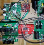
I have connect everything to my Red Baron rig. It runs perfect.
Wave IO --> S/PDIF backdoor I2S input --> FIFO --> Isolator --> Dual Clock --> Red Baron --> Tube-I-zator
The 1st Salas SSLV (6V) is for the Wave IO, S/PDIF module, FIFO and Uplink of the Isolator.
The 2nd Salas SSLV (5V) goes only to the Dual Clock and downlink of the Isolator.
As i know from my modified Teralink X2 USB to I2S converter it was a major step forward, after i omit the onboard 3.3V reg. and use a 3.3 SSLV direct.
Is it also possible to omit the dual clock onboard reg. an use a SSLV 3.3V here?

good to have you back here!
I have connect everything to my Red Baron rig. It runs perfect.
An externally hosted image should be here but it was not working when we last tested it.
Wave IO --> S/PDIF backdoor I2S input --> FIFO --> Isolator --> Dual Clock --> Red Baron --> Tube-I-zator
The 1st Salas SSLV (6V) is for the Wave IO, S/PDIF module, FIFO and Uplink of the Isolator.
The 2nd Salas SSLV (5V) goes only to the Dual Clock and downlink of the Isolator.
As i know from my modified Teralink X2 USB to I2S converter it was a major step forward, after i omit the onboard 3.3V reg. and use a 3.3 SSLV direct.
Is it also possible to omit the dual clock onboard reg. an use a SSLV 3.3V here?
Attachments
Last edited:
Hi Ian,
Glad you're back, I have a few questions
I bought the sis clock board but my situation has changed so I'm gonna be needing the SPDIF output board and on the receiving end there's a TI SRC4382 which says in the datasheet Master Clock Input (MCLK) Frequency, fMCLK MAX 27.7 MHz.
1) So I guess my best solution is buying a pair of crystek 22/24 clocks and using the dual XO board?
2) Is there any advantage in this case using the isolator board with the dual XO board since the SPDIF board receives power from the FIFO board through the ribbon cable? Or can I remove the ribbon cable and power the spdif board from the same powersupply as the dual XO board after the isolator/ Or maybe another powersupply if there's any advantage to that?
Thanks
Hi edbk,
1, Since the max frequency is 27MHz, you can still go ahead with si570 clock board by setting the frequency to 22/24Mhz manually. Dual XO clock board would be another option if you want.
2, Only DAC gains form an isolator at finial stage. For your application, I don't think you need it.
Regards,
Ian
Welcome back Ian!
On the weekend just gone I finally had all the parts I needed in place, so I soldered up one of my TPS7A regulator boards as well as a v2.5 isolator board and modified one of my spare regulators to give me 6V for the FIFO (I had no adjustable regs here only fixed output regs at voltages that weren't suitable for the FIFO). Finally I was able to power up my own FIFO. All works as intended!
Thanks hochopeper, great to know that.
Ian
Hi Ian,
good to have you back here!
I have connect everything to my Red Baron rig. It runs perfect.
An externally hosted image should be here but it was not working when we last tested it.
Wave IO --> S/PDIF backdoor I2S input --> FIFO --> Isolator --> Dual Clock --> Red Baron --> Tube-I-zator
The 1st Salas SSLV (6V) is for the Wave IO, S/PDIF module, FIFO and Uplink of the Isolator.
The 2nd Salas SSLV (5V) goes only to the Dual Clock and downlink of the Isolator.
As i know from my modified Teralink X2 USB to I2S converter it was a major step forward, after i omit the onboard 3.3V reg. and use a 3.3 SSLV direct.
Is it also possible to omit the dual clock onboard reg. an use a SSLV 3.3V here?
Hi dvb-projekt,
Your system looks great. How's fifo going with your Red Baron and your glass IV?
Ian
Steps to Si570 Clock Board
Si570 clock board is the best 90/98 MHz low jitter clock source we could touch so far except we get OEM CCHD950s at those frequencies. But Si570 clock board is a bit difficult to run than the dual XO clock board. There are two reasons:
1. It’s a much bigger challenge to a low noise power supply with output at 100mA than at 20mA.
2. To keep low jitter performance, MCLK around 100Mhz needs better coaxial cables and other conditions connected to RF transmission than frequency below 50Mhz.
So, one of the key things to the Si570 clock board is the power supply (Cables will be discussed later). That’s why I keep it open and flexible after four times re-design the board. I left this part to DIYers to decide what is the best power supply solution according to their personal preference.
We need figure out the following questions:
1. What is the best power supply for the Si570 clock board? Low noise regulator or 3.2V LiFePO4 battery direct?
2. If we use a low noise regulator, what is the best suitable one?
3. TPS7A4700 is the best integrated low noise regulator we could find so far, if we decide to use it, what are the best output capacitors or combination?
4. If we decide to use a low noise regulator, what is the best DC input feed to it? A battery pack or a bigger shunt reg?
But we have to set up a power supply reference before we doing any try out to avoid mix up. I suggest using a 3.2V LiFePO4 battery cell or cells in parallel directly as the reference. An isolator between fifo and clock board is also be required to avoid any RF noise introduced from ground plate. Any change needs to be compared with this reference by listing test to decide good or not. I’ll post pictures of this reference setting later.
Have fun with R&D
Ian
Last edited:
Ian,
Any chance you'd be able to provide accurate dimensions for the optional rf shield? Do you have a part number handy that would be suitable, I've had a look through the Laird Technologies parts that look like they should fit, the corners on their shields are a bit different to the mounting positions that you've provided on the pcb though.
My DAC sits directly underneath a shelf that has my iMac on it along with typically phone, camera(s), ipad and everything else (arduino, beagle bone etc etc) are all nearby so I think the peace of mind of the additional rf shield seems worthwhile in my application.
Cheers,
Chris
Ian,
Any chance you'd be able to provide accurate dimensions for the optional rf shield? Do you have a part number handy that would be suitable, I've had a look through the Laird Technologies parts that look like they should fit, the corners on their shields are a bit different to the mounting positions that you've provided on the pcb though.
My DAC sits directly underneath a shelf that has my iMac on it along with typically phone, camera(s), ipad and everything else (arduino, beagle bone etc etc) are all nearby so I think the peace of mind of the additional rf shield seems worthwhile in my application.
Cheers,
Chris
The size of the optional shield is 10*13.5 mm, not a standard one. You have to make it by yourself if you want. Please be careful not to short anything else on the PCB, connecting to GND only.
Regards,
Ian
Hi dvb-projekt,
Your system looks great. How's fifo going with your Red Baron and your glass IV?
Ian
It runs perfect.
I did some modifications on the Red Baron that -ecdesigns- recommended.
Therefore i must build up two new pcb´s and i am still in burn in phase.
The first few hours are very promising.
Perhaps you could send me a PM for the direct 3.3V input of the dual clock board.
Even if i ask it before, did you see a chance to get the same input running after powering up the S/PDIF ?
Now it starts every time with the optical input, witch is not nice if you use another input e.g. I2S backdoor...
Cheers,
Oliver
Good to know that, Oliver
Do you want to run the dual xo from 3.3V battery direct? You have to remove the on board low noise LDO. But I don't think it's problem for you. Let me know if you need a picture of the set up.
The source selecting was done by FPGA hardware, the last setting can not be saved and re-called. It's not difficult to design a panel board to take care of the control and display. Last setting can be re-called on next power up. A small MCU would be good for this kind of application, or you can use an Arduino.
I2S back door...? Do you need fixing it?
Regards,
Ian
I would be interested in a photo too! Thanks.Do you want to run the dual xo from 3.3V battery direct? You have to remove the on board low noise LDO. But I don't think it's problem for you. Let me know if you need a picture of the set up.
Ian
- Home
- Source & Line
- Digital Line Level
- Asynchronous I2S FIFO project, an ultimate weapon to fight the jitter