Hi, I have a question about asymmetrical order and frequency crossover.
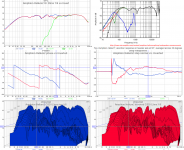
I have Visaton BG 20 "full-range" driver, but since it is very poor above 10kHz I have decided to add tweeter Visaton TW 6 NG.
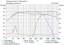
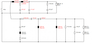
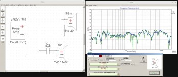
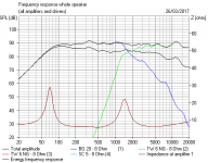
BG 20 has bump from 1kHz to 9kHz so I came up with idea of using 6db low pass filter at 1kHz on BG 20 and 12db (LR2) high pass filter at 4.5kHz on TW 6. It works quite well in simulation, but I'm worried it might not work well due to some side effects (phase, ...). BG 20 would definitely need notch filter, if used above 1kHz.
Here is simulation:
Would this work?
Do you have any considerations or suggestions about this?
I have Visaton BG 20 "full-range" driver, but since it is very poor above 10kHz I have decided to add tweeter Visaton TW 6 NG.
BG 20 has bump from 1kHz to 9kHz so I came up with idea of using 6db low pass filter at 1kHz on BG 20 and 12db (LR2) high pass filter at 4.5kHz on TW 6. It works quite well in simulation, but I'm worried it might not work well due to some side effects (phase, ...). BG 20 would definitely need notch filter, if used above 1kHz.
Here is simulation:
An externally hosted image should be here but it was not working when we last tested it.
Would this work?
Do you have any considerations or suggestions about this?
I should have answered your question a little more.
Assymetrical crossovers are very common, but the details are driven by phase AND amplitude matching. You will need to examine both closely as you design.
There is a thread in the software section for XSim, which includes some designs. You can use them to learn about what is involved, or you can start here:
https://speakermakersjourney.blogspot.com/2016/02/the-lm-1-bookshelf-version.html
Look at the last two links under "Design Documents"
Right!
Also make sure the FRD data includes phase, XSim won't create it, and it must be there. Same for your impedance data. So, Distance, FRD/acoustic phase and impedance with electrical phase, all must be in your sim to get accurate results.
There is no absolute requirement of distance. What there is are rules of maximum distance at given frequencies, but these are not set in stone, and often challenged, since they will integrate better with longer listening distances.
Best,
E
Last edited:
I don't see why you should use anything but Visaton Boxsim for this.
I had a look at the issues here, and they are fierce.
BG 20 - 8 Ohm
The TW70 seemed a much better idea, BTW.
TW 70 - 8 Ohm
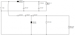
Best idea I saw was a Troels Gravesen project:
Monacor SP200X +
But you're not going to like it. 4th order on First Draft! Lots of impedance correction too. Nothing wrong with that, but hard to build.
I had a look at the issues here, and they are fierce.
BG 20 - 8 Ohm
The TW70 seemed a much better idea, BTW.
TW 70 - 8 Ohm
Best idea I saw was a Troels Gravesen project:
Monacor SP200X +
But you're not going to like it. 4th order on First Draft! Lots of impedance correction too. Nothing wrong with that, but hard to build.
Attachments
I didn't use Boxsim and XSim, because they are not for Linux.
TW 70 only gets to ~15kHz, TW 6 NG gets to 20kHz easily.
Hm, looks really good, but such crossover would be too expensive (for cheap drivers). Why two TW 70? For better power handling, because they are crossed low?
TW 70 only gets to ~15kHz, TW 6 NG gets to 20kHz easily.
Hm, looks really good, but such crossover would be too expensive (for cheap drivers). Why two TW 70? For better power handling, because they are crossed low?
As close as possible would be best than?There is no absolute requirement of distance. What there is are rules of maximum distance at given frequencies, but these are not set in stone, and often challenged, since they will integrate better with longer listening distances.
As close as possible would be best than?
Yes. Exactly.
Some get pretty serious about keeping the center to center distance less than some value based on the crossover point, but at listening distances I feel that matters much less than the angle, which is usually very small.
Your brain/ear/head/body combination is able to discriminate among different angles, which cause comb filtering effects. To me, that's much more important to worry about than "I have a crossover point of 3kHz, therefore my tweeter needs to be less than X cm away from the midrange"
What will matter, without argument, a great deal is the acoustic offsets, because that will create major fr issues and lobing if not handled well.
Here is one link on how to find this:
https://speakermakersjourney.blogspot.com/2016/02/lm-1-testing-driver-distances.html
Best,
E
Best,
E
Last edited:
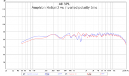
This does not apply to asymetrical xos! Just look at step response.When you have all of this in, reverse the tweeter in your sim and examine the FR. Should create a dip that is deep, wide and symmetrical.
An example attached, Amphion Helium, bass polarity switched. Sorry I don't have separate responses for bass and tweeter
Attachments
The shape of the dip has to do with the electro-acoustic phase matching, not just electrical. If this were all op-amps you'd be correct.
I have 2 assymetrical crossover design on my screen, and it pretty much applies. It's not "as perfect" as my symmetrical design, but it is pretty close.
Best,
E
I have 2 assymetrical crossover design on my screen, and it pretty much applies. It's not "as perfect" as my symmetrical design, but it is pretty close.
Best,
E
Last edited:
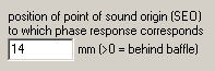
I measured acoustic offset to be 1.15 in (29 mm). According to Boxsim data it is 36 mm (1.4 in). Difference is probably due to vertical distance (mic was more on woofer's axis).
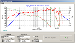
I simulated some crossover in Boxsim and wanted to double check it in XSim. I have extracted frequency response from Visaton's images to *.frd and added phase with phase extractor. Copied crossover from Boxsim to XSim and imported *.frd and *.zma.
Result was very similar with no offset, but different with offset (no matter 1.15 or 1.4 in). When I selected FRD phase source derived in XSim, it matched with offset (1.15 or 1.4 in), but not without offset.
Somehow frequency response must already contain that information. What SPL at 1m/1w actually means? 1m from speaker or it's acoustical center?
Attachments
- Status
- This old topic is closed. If you want to reopen this topic, contact a moderator using the "Report Post" button.
- Home
- Loudspeakers
- Multi-Way
- Asymmetrical crossover