Current status.
Hi,
I defaulted my stated time of completion. Been very busy with real work !
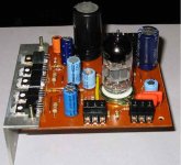
I finally completed a pcb design for this - a 4x4 inch board. Has everything on it except the input/output sockets and the transformer. If I complete the board (hand painted!) this evening , I will try to post some pics and maybe some test results.
The board has several jumpers. Had no time to refine the design.
Next week is a very busy week so I must try to get it done now.
Cheers.
Ashok.
Hi,
I defaulted my stated time of completion. Been very busy with real work !
I finally completed a pcb design for this - a 4x4 inch board. Has everything on it except the input/output sockets and the transformer. If I complete the board (hand painted!) this evening , I will try to post some pics and maybe some test results.
The board has several jumpers. Had no time to refine the design.
Next week is a very busy week so I must try to get it done now.
Cheers.
Ashok.
Board finally ready.
The board is ready . The power supply however has a problem. I am getting only 17 volts in place of 40 volts. The 2200uF cap is heating up. A quick look shows everything is OK but something must be wrong. Will look at it in the morning.
I will try to attach a picture here.
Test results as soon as the power supply is fixed.
Cheers.
Ashok.
Finally done it !
Hi Needtubes and others,
I got the phones amp to work this morning. The 2200uF/50 V power supply cap was heating up fast enough to blow up. It did not measure as a short or show low resistance. I replaced with another one of the same type. Same problem !! So I went into the market and got a Samsung(?) 4700uF/50V cap and it works fine.
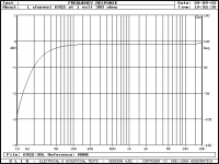
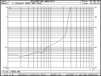
I am attaching the frequency response and the distortion curves.
I played music through the device and used a Sennheiser HD580. It sounds very good. For the outlay I think it sounds great. Great bass and clean all through to hf. The transients are great also.
Go build one. You won't regret it. Some suggestions from me. The heat sink shown in the picture posted earlier is enough for a quiescent current of about 14mA through the MOSFET's. I tried 60mA also and that will need fins. It gets pretty hot - but still touchable if no fins are added ( at 60mA).
14mA is enough for a Sennheiser ( 300 ohms and 97db/mW). But for less sensitive phones and lower impedance you need more current. The limiting factor is clipping on the bottom of the waveform when the current source goes dry. Into a 22k load the amp gives just under 28 volts peak to peak.
The distortion rises rapidly at the point where the load current approaches the current source current. So to get more output you need to up the quiescent current ( for lower headphone impedances).
With 14mA it goes very loud and also sounds very clean. The input capacitor is 0.47uf . You can eliminate this if the signal available is dc free. This may clean up the transients and HF even more.The graph shown has a 1db scale per indicated division.. As you can see it is just about -0.8db at 20Hz.
I could not hear any hum or hiss at full volume .I will try this out when it is absolutely silent and on a HD475 which is quite clinical.
If anyone wants more details I can make it up into a pdf file and email it to you including the pcb layout.
Cheers.
Hi Needtubes and others,
I got the phones amp to work this morning. The 2200uF/50 V power supply cap was heating up fast enough to blow up. It did not measure as a short or show low resistance. I replaced with another one of the same type. Same problem !! So I went into the market and got a Samsung(?) 4700uF/50V cap and it works fine.
I am attaching the frequency response and the distortion curves.
I played music through the device and used a Sennheiser HD580. It sounds very good. For the outlay I think it sounds great. Great bass and clean all through to hf. The transients are great also.
Go build one. You won't regret it. Some suggestions from me. The heat sink shown in the picture posted earlier is enough for a quiescent current of about 14mA through the MOSFET's. I tried 60mA also and that will need fins. It gets pretty hot - but still touchable if no fins are added ( at 60mA).
14mA is enough for a Sennheiser ( 300 ohms and 97db/mW). But for less sensitive phones and lower impedance you need more current. The limiting factor is clipping on the bottom of the waveform when the current source goes dry. Into a 22k load the amp gives just under 28 volts peak to peak.
The distortion rises rapidly at the point where the load current approaches the current source current. So to get more output you need to up the quiescent current ( for lower headphone impedances).
With 14mA it goes very loud and also sounds very clean. The input capacitor is 0.47uf . You can eliminate this if the signal available is dc free. This may clean up the transients and HF even more.The graph shown has a 1db scale per indicated division.. As you can see it is just about -0.8db at 20Hz.
I could not hear any hum or hiss at full volume .I will try this out when it is absolutely silent and on a HD475 which is quite clinical.
If anyone wants more details I can make it up into a pdf file and email it to you including the pcb layout.
Cheers.
Attachments
The distortion graph.
Please note that you could get more output voltage by increasing the quiescent current in the mosfet's by decreasing the resistor in the source of the bottom MOSFET. I used 390 ohms for 14mA current. The voltage across it is about 5.5 volts with a Zener of 9.1 volts. With an 82 ohms resistor the current is above 60mA.
You can improve the Lf response by increasing the input cap. I personally prefer to remove the cap. I will try this tomorrow. Small dc offsets from the source will possibly not matter much at all.
Cheers.
Attachments
Improvements -already!
I decided to implement some changes to see how the amp sounds.
First of all with a HD475 phones I can hear no hum or hiss at full volume. It also sounds wonderful right across the band. The whole unit is pretty inexpensive to build and there are no exotic parts . The input cap is an orange drop 0.47uF/100v cap. The resistors are all carbon film and electrolytic capacitors are Philips / Samsung and a couple of local brands. The tube is a Sovtek 6922 .
The transformers used are 15-0-15 / 1 A and a 6-0-6 /1A type.
I remember noticing that many members consider the bypass capacitor on the cathode resistor to be sonically bad. So I removed the cap after the initial tests. I feel that the resistor sounds better without a bypass capacitor. It looks like low level detail comes out better. An example is the sound of a bell. Without a capacitor I can hear the decaying sound 'very' clearly.
I must put back the cap to compare again and make sure I am not imagining the difference! The mind can play tricks!
Would anyone care to try out this mod and comment on it.
Anyway my final circuit will not contain the bypass cap.
It sounds great and I think it will also be a very good single stage (inverting ) pre amp also. It will be able to handle any type of cable on the output as the load is handled by the MOSFET'S. I will put up the response of the amp with the input cap removed.
If anyone can try out 'exotic' parts , please let us know how it works out.
Cheers.
More test results.
1. I removed the input capacitor . So now the response is ruler flat up to about 10KHz and drops about 0.2 db at 20 KHz.
2. I increased the quiescent current to 44mA as my other phones are less than 100 ohms.
The unit sounds great. You can hear very small changes in a mix - something I never heard before. Voice is great and I am really impressed with the amount of low level detail I can hear. I am really glad I built this unit.
Thanks to Needtubes for pushing me to get it done and post the results. It speeded up the process of building it tremendously. So Needtubes can have the spare board that I have. Email me you address and I will have the board mailed to you - if you want the board.
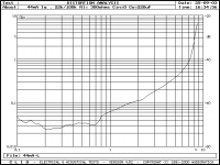
The distortion curve with 44mA is attached. As you can see the overload point is much higher than before. I forgot to mention that the output impedance is below 0.01 ohm over most of the band and rises to about 0.04 ohms at 20 Khz.. That's real low ! This unit could also be used as a pre amp I guess .The noise floor seems to be below -90db ( ref 1 volt output) as seen on the FFT. Voltage gain is just under 4 . That should be enough for most applications.
Cheers.
1. I removed the input capacitor . So now the response is ruler flat up to about 10KHz and drops about 0.2 db at 20 KHz.
2. I increased the quiescent current to 44mA as my other phones are less than 100 ohms.
The unit sounds great. You can hear very small changes in a mix - something I never heard before. Voice is great and I am really impressed with the amount of low level detail I can hear. I am really glad I built this unit.
Thanks to Needtubes for pushing me to get it done and post the results. It speeded up the process of building it tremendously. So Needtubes can have the spare board that I have. Email me you address and I will have the board mailed to you - if you want the board.
The distortion curve with 44mA is attached. As you can see the overload point is much higher than before. I forgot to mention that the output impedance is below 0.01 ohm over most of the band and rises to about 0.04 ohms at 20 Khz.. That's real low ! This unit could also be used as a pre amp I guess .The noise floor seems to be below -90db ( ref 1 volt output) as seen on the FFT. Voltage gain is just under 4 . That should be enough for most applications.
Cheers.
Attachments
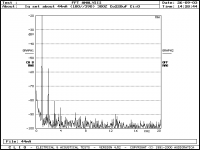
The FFT.
I have attached the FFT made at a quiescent current of 44mA ( through the MOSFET's) and an output of 1.45V.
Load was 300 ohms.
The noise level as seen on the FFT is below -90db ( with reference to this signal the S/N should be about -93db ).
I plan to plug in an ECC tube and see what results I get !
Cheers.
Attachments
Quick tests with different tubes.
I just plugged in an ECC81 ( NOS Mullard ) and a ECC82 (RFT).
The ECC82 had slightly higher distortion than the 6922.
The frequency response is -0.5 db down at 20 Khz. The 6922 was just about -0.2db at 20Khz.
The ECC 81 was surely poorer. The distortion was significantly higher and the frequency response was -1db at 20 Khz.
Frankly I never even expected so much out of these tubes at such low voltages. The supply voltage is just about 37 volts with anode voltage at about 20 volts.
I must try out the units with headphones and see how they differ while playing music. The good news I guess is that one can get away with an ECC82 also. This is a LOW cost headphone amp and performs very well.
Cheers.
Hi,
At low plate voltages such as the ones you're using it comes as no surprise that the 6922 comes out best.
It's still relatively linear whereas the others aren't.
Cheers,")
The supply voltage is just about 37 volts with anode voltage at about 20 volts.
At low plate voltages such as the ones you're using it comes as no surprise that the 6922 comes out best.
It's still relatively linear whereas the others aren't.
Cheers,
Hello-
Life became busy for me recently.... so I have not posted as much.
I am glad your results turned out well. Perhaps I should begin collecting my parts... I think I have some laying around already. My cans will be the HD580s, so everything should work well.
EDIT: I cannot seem to email you- it says I don't have permission.
Life became busy for me recently.... so I have not posted as much.
I am glad your results turned out well.
Perhaps I should begin collecting my parts... I think I have some laying around already. My cans will be the HD580s, so everything should work well. EDIT: I cannot seem to email you- it says I don't have permission.
Email disabled.
Hi Needtubes.
Your email is disabled too !
You can email me at
spam_ashokm@sify.com_spam
Remove the underscore (_) and the (spam).
I get so much junk mail that I am afraid to put up the email id by itself.
Cheers.
Ashok.
Hi Needtubes.
Your email is disabled too !
You can email me at
spam_ashokm@sify.com_spam
Remove the underscore (_) and the (spam).
I get so much junk mail that I am afraid to put up the email id by itself.
Cheers.
Ashok.
6922 best option.
Hi Frank,
Yes the 6922 is suited for low voltage applications. I however did not expect any of the ECC series to be anywhere near the 6922 as the voltages were so low.
Though they do have much larger distortion figures than the 6922 it might appear that they "might" sound acceptable at low volume.
Well my listening test confirmed that the 6922 is far better than either ECC tube that I tried. The ECC82 is an acceptable substitue if one does not have a 6922/6DJ8 at hand. But the 6922/6DJ8 will have to be used eventually if one plans to use this as a headphone amp regularly.
I found the sound of the 6922 easier on the ear and cleaner than the ECC82. The ECC81 does not even figure over here.
Iused a Marantz CD67SE-II that I modified , as the source.
Transients are really great on a HD580 and HD475. The HD 580 has of course more low end than the 475. The 475 however sounds "faster" especially with transients.
The circuit has only one capacitor in the signal path. The output capacitor - a 100 or 220 uf type. I don't have a Black Gate to see if there can be any difference between that and the Philips type that I have used. If used as a preamp however , I can change this to a 1uF polyester type - improving the audio path ? In fact , maybe I can connect both a 100uF and 1uFPolyester and take separate outputs to a headphone socket and the other to an RCA socket ( for use as a pre amp). Is this a good idea?
Cheers.
Hi,
Certainly, you could do this.
But why polyester caps?
Generally speaking any metallised polypropylene cap should be a better coupling cap.
If you can't find those the metallised polycarbonate one are second best.
Just don't load your headphone/preamp with both the headphones and amp at the same time.
Cheers,
If used as a preamp however , I can change this to a 1uF polyester type - improving the audio path ? In fact , maybe I can connect both a 100uF and 1uFPolyester and take separate outputs to a headphone socket and the other to an RCA socket ( for use as a pre amp). Is this a good idea?
Certainly, you could do this.
But why polyester caps?
Generally speaking any metallised polypropylene cap should be a better coupling cap.
If you can't find those the metallised polycarbonate one are second best.
Just don't load your headphone/preamp with both the headphones and amp at the same time.
Cheers,
Coupling caps.
Hi Frank,
Thanks for you post. I was generally mentioning about caps and didn't really mean polyester specifically. I just typed what came to mind. Film versus electrolytic.
Here we do have a problem getting what we want , though generally plenty of 'general' components are available.
We do get polycarbonate capacitors and I have used a few. I am not sure about their sonic capabilities against the 'better known' brands. We don't have much of a choice.
The 1uF that I used is from Philips and is marked 1uF/K/250V/MFC. The other types have axial leads and need more board space and worth it only if they are better. I haven't really compared them. Maybe I should.
Have you any experience with (orange) Philips capacitors like the 1uF I mentioned? ( like the Sprague Orange Drop ?)
Cheers.
Ashok.
Hi,
I know which ones you mean but I've never used them for audio projects.
Maybe someone else has?
Cheers,
Have you any experience with (orange) Philips capacitors like the 1uF I mentioned?
I know which ones you mean but I've never used them for audio projects.
Maybe someone else has?
Cheers,
Test as a pre amp.
I did a hasty test as a pre amp.
First I played the CD player direct to an Alps Blue pot and then into the power amp. Then I played the same music through the new 6922 phones amp. Cd player to Volume pot to 6922 amp. Output of 6922 amp to power amp ( input pot at max position).
It sounds good with a few reservations. Bass is a bit smeared. It sounds 'a bit' wooly in comparison. Mids and hf seem to be very good. It is 11pm here so I can't turn up the volume. Will do that tomorrow. I will also remove the otput cap on the phones amp
( 220uF at the moment ) and use a better quality film capacitor. Maybe the bass will improve. The bootstrap capacitor 'could have been' a Black Gate ! I will also try high speed diodes in the power supply and also a tube rectifier ( later).
For the outlay I think this has worked out very well. I am especially pleased that there is no audible hum or hiss - a big relief. Now I can work on the circuit and refine it some more. It should be hard to beat at the price.
BUT compared to my new tubed passive eq RIAA amp and vinyl playback system , the CD player sounds FLAT ! There is so much "more" information on vinyl. After hearing it for a few weeks now , so much seems missing. I have CD versions of vinyl discs for comparison. What a diff. !
Cheers.
Caps.
Hi Frank ,
The MFC caps are metallised polycarbonate I think. Philips has another set of codes on their caps shown on the web. KC stands for polycarbonate and M for metallised. So I guess this must be polycarbonate.
I tested the amp at fairly high volume and the difference between the 6922 and ECC82 becomes very apparent. But then it is not fair to compare the ECC82 when it is being run at a voltage where it was not meant to function. I must try an ECC82 with a 250 or 300 volt supply and see how that will compare with the 6922. Would you have any idea?
6922 at about 20 volts anode voltage ( +40 Volt supply ) and
ECC82 at about 125 volts anode voltage (at +250volts supply ).
Cheers.
Ashok.
Hi,
That's what I think as well but often the F stands for foil.
In this case I'd doubt it but you never know.
Metal and foil caps are even better than plain metallised ones so, maybe you're in luck.
For the record:
M = Metallised.
K = ?
T = Polyester.
C = Polycarbonate.
P = Polypropylene.
That's just the most common ones.
To be honest I wouldn't even bother with the ECC82 their distortion spectrum is nothing to write home about.
Rather I'd rework the 6922 circuit so it runs from approx. a 200 VDC supply and revise the bias settings.
This should give you more dynamic range and hopefully even less distortion.
Cheers,
The MFC caps are metallised polycarbonate I think.
That's what I think as well but often the F stands for foil.
In this case I'd doubt it but you never know.
Metal and foil caps are even better than plain metallised ones so, maybe you're in luck.
For the record:
M = Metallised.
K = ?
T = Polyester.
C = Polycarbonate.
P = Polypropylene.
That's just the most common ones.
I must try an ECC82 with a 250 or 300 volt supply and see how that will compare with the 6922. Would you have any idea?
To be honest I wouldn't even bother with the ECC82 their distortion spectrum is nothing to write home about.
Rather I'd rework the 6922 circuit so it runs from approx. a 200 VDC supply and revise the bias settings.
This should give you more dynamic range and hopefully even less distortion.
Cheers,
I had a couple of people asking about the headphone amp circuit.
I think it is linked in this thread.
http://www.diyaudio.com/forums/showthread.php?threadid=18941&highlight=hybrid+headphone+amp
(post#6)
About running at high voltage and low voltage.
I'll try to check that out and post the results. The board is somewhere around. I'll have to look for the pcb layout . It's not on this computer for sure.
One catch about higher voltage operation is the power dissipation of the output stage . We need the current for low impedance headphones but do not need the extra voltage possible. Maybe some mods are possible. Let me work on that ......later.
Cheers,
Ashok.
- Status
- This old topic is closed. If you want to reopen this topic, contact a moderator using the "Report Post" button.
- Home
- Amplifiers
- Headphone Systems
- ashok's tube/ss hybrid headphone amp