Here are some recordings of the phase noise of the oscillator in the SAA7220.......one of my all time favorite parts.
[Snicker, snicker.........]
As I have been ill the last few days, and don't feel like thinking up another clever April Fool's Joke, this will have to suffice. But make no mistake.......these recordings are for real.
Now......if we can get Phred to upload the X-Files theme........
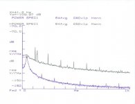
First off.........a recording of the SAA7220 in a CDB-472, stock configuration. The reference oscillator is one of the low-noise jobbies that I have posted here. Note all the line related crap, as this player has tons of ground loops.
[Snicker, snicker.........]
As I have been ill the last few days, and don't feel like thinking up another clever April Fool's Joke, this will have to suffice. But make no mistake.......these recordings are for real.
Now......if we can get Phred to upload the X-Files theme........
First off.........a recording of the SAA7220 in a CDB-472, stock configuration. The reference oscillator is one of the low-noise jobbies that I have posted here. Note all the line related crap, as this player has tons of ground loops.
Attachments
For reference...........
Here is the phase noise of one of my oscillators.
It is recoreded at 10 dB higher in level.
Moral of the story:
Use a good oscillator for your clock.
And a quiet regulator.
Get rid of ground loops.
Make a separate distribution scheme. Do not use the internal buffer in the filter chip to distribute the clock signals.
I'm really sick today.......so "forget you guys.....I'm going home......"
Jocko
Attachments
Excellent stuff
Jocko,
Thanks for taking the time out from your sick bed to post those - excellent stuff.
Were the phase noise measurements made using readily available methods?
I've been thinking about comparing to a known 'good' oscillator (by mixing, and gathering the data via a sound card), but haven't got my head around the effects of non-ideal behaviour in the reference clock on the output signal (mathematically). I think it's simple and will just limit the ultimate measurement noise floor?
I know self-triggered measurements (e.g. on a 'scope) give misleading results based on timebase settings.
Andy
The graphs may be somewaht misleading, as the tape recorder used intorduced some noise, and I had to bandlimit things to get the file size under 100k.
The real noise of my oscillator is not even on the scale on my RTA, whereas the SAA7220 stands out like a sore thumb. Remember, I amplified mine 10 dB so that it would not be drowned out by the noise floor of the cheap tape recorder.
The way it is done........a known good oscillator is phase locked to the unit you want to test. Both are then fed into a double-balanced mixer.
I might make some plots on my H-P FFT, but I don't think that they would scan OK.
Yes, I am really am sick today, but I could not let April 1 pass without doing something out of the ordinary. Feel free to ask any questions, but I may not answer right away.
Jocko
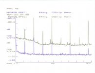
FFT plots......
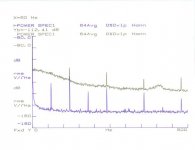
The top plot is the SAA7220, with the low-noise regulator.
Bottom plot is my oscillator. The hump at 41 Hz seems to be the noise contribution of the PLL, as that is close to the natural frequency that I calculated.
Basically, mine is 20 dB lower noise.
Jocko
The top plot is the SAA7220, with the low-noise regulator.
Bottom plot is my oscillator. The hump at 41 Hz seems to be the noise contribution of the PLL, as that is close to the natural frequency that I calculated.
Basically, mine is 20 dB lower noise.
Jocko
Attachments
Thanks again
Thanks for the info Jocko,
Being an typical engineer type I hate to re-invent wheels, when there's perfectly good ones in existence, so could you be persauded into providing some basic schematics for the phase noise measurement.
I'll have to think about it otherwise, and you're bound to be better at it than me")
Pretty please..
Andy.
Thanks for the info Jocko,
Being an typical engineer type I hate to re-invent wheels, when there's perfectly good ones in existence, so could you be persauded into providing some basic schematics for the phase noise measurement.
I'll have to think about it otherwise, and you're bound to be better at it than me
Pretty please..
Andy.
Hello Jocko,
I did what I could to make this FFT trustworthy, FFTed it also in some other analyzers… Still I don’t say I did the job, FFT of the longer signals (as these are) could be misleading, FFT of the lower frequencies is problematic in itself… but it is definitely possible you have a hump at somewhat lower frequency...
Thanks for sharing.
Pedja
Attachments
Ignore the first graph........
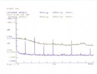
The hump at 41 Hz bugged me, so I changed the op-amp in the integrator from one audiophile approved chip to another. Problem solved.
Somehow, in the process, I picked up a ground loop in the reference. I feel too sick to care why today, so you guys will just have to deal with it. Pretend the 60 Hz isn't there........
Anyway......first graph: 472 in stock form, with my ground loop skewed oscillator below.
Attachments
Hold on to your hats........
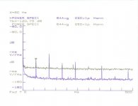
Then I turned all the other circuitry in the 472 off. Most notably, the micro.
Of course, this is not possible in real life, but the SAA7220 is only 12 dB worse now.
Hope this is interesting for you guys to get ideas on how to improve your CDPs. I could have stayed in bed where, I belong............but no...............
This is what all of you will be like if you do this for a living after 30+ years.
Signoro Llyod, I hope you are reading this. I somehow suspect your wife is not looking forward to you turning out like me.
Quit while you are ahead!!!!!!!!!!
Oh, yeah.......Andy.........
Wenzel has a good tutorial on their web site about this stuff. I'll let them explain it to you.
Jocko
Attachments
Re: Hold on to your hats........
Oooooooh Nooooooooo! It's too late... She's looking over my shoulder, hands on hips as I type this... I'm in in for it big time now. No honey, I'm not selling all my scopes except one ....
help.. help......AAARG!!!..........
mlloyd1
Oooooooh Nooooooooo! It's too late... She's looking over my shoulder, hands on hips as I type this... I'm in in for it big time now. No honey, I'm not selling all my scopes except one ....
help.. help......AAARG!!!..........
mlloyd1
Jocko Homo said:This is what all of you will be like if you do this for a living after 30+ years.
...
Signoro Llyod, I hope you are reading this. I somehow suspect your wife is not looking forward to you turning out like me.
...
Quit while you are ahead!!!!!!!!!!
...
Jocko
That was like a Monty Python's sketch! And now for something completely different...
Stereoplay magazine publish a jitter measurement in all their CD/SACD/DVD-player tests. Apparently, the output a 1 kHz test signal and look at the smearing of the floor close to the fundamental. There are substantial differences in the form and amplitude of their graphs. They even seem to be able to compute a jitter in ps from this.
I assume this requires an ADC with low aperture jitter of its own, driven from a very good clock.
- Status
- This old topic is closed. If you want to reopen this topic, contact a moderator using the "Report Post" button.
- Home
- Source & Line
- Digital Source
- As promised.......the Phase Noise Files.....