Hello Hercules,
I am no longer working for Philips, But I might be able to help you.
The 930 product was certainly a nice product. A lot of the usual speaker/cabinet/cross-over design issues were "ironed" out digitally. The amplifier however was analog.
Regarding your DCC player the best is to try first:
General Office Address
Philips Electronics Hong Kong Ltd.
28/F, Hopewell Center
17 Kennedy Road, Wanchai
Hong Kong
Phone: +852 2821 5888
Customer Service Information
Consumer Electronics
Phone: +852 2619 9663 (Customer Service Center)
Operating hours: 8:30am - 5:30pm (Mon - Fri)
Daily except Saturday, Sunday and public holidays
Email inquiry: pceinfo.hk@philips.com
The service obligation time is normaly 7 years after production stop. I guess it will not that difficult to get a service documentation for that product. Getting very specific (mechanical) parts migth be difficult.
Success!
Ward
Dear Ward:
Actually I send the DCC to Philips Hong Kong for service after 1 1/2 year of Philips no longer sell DCC. they said the MR head is bad and no longer have stock... so I'm looking for any chance for fixing out of Hong Kong, especially in Holland!!
anyway, thanks for your help and your information!!! the DSS system is very interesting to me!!
TDA8924 - subwoofer amp
Lieven,
Did you receive your samples from Philips? If so, how does this chip sound?
I'd like to use the TDA in bridged mode for a subwoofer amplifier (bridged mode does 240W in a small package, low component count, smaller heatsink and power supply needed).
The Philips site says that samples are available but it is not clear how to order samples (I'll pay for the chips but no distributor has them in stock yet).
Regards,
Dean
Re: Anyone trying the philips Class D implementation
That is true. If you look at the data sheet of the TDA8929T modulator-only chip you will see how the modulator works. It uses feedback from the power pulse output. This is the same thing as Tripath does, although the Tripath modulator works somewhat different.
Cheers")
deandob said:The other interesting thing about this chip is that it mentions high power supply ripple rejection, yet most class D implementations have very low or no (eg. Equibit) supply rejection.
Regards,
Dean
That is true. If you look at the data sheet of the TDA8929T modulator-only chip you will see how the modulator works. It uses feedback from the power pulse output. This is the same thing as Tripath does, although the Tripath modulator works somewhat different.
Cheers
There seems to be some confusion here. From what I understand the Philips “UCD” is based upon a Hysteresis Controller, i.e. no fixed Carrier (Clock) just like the first SMPS designs – where as the TDA8924 is based on more conventional Class D technology, i.e. fixed Clock frequency.
If you Email me I will send you a paper which appears very similar to what Philips are calling “UCD”
Sorry I cannot “Post it” as it’s about 250KB
If you Email me I will send you a paper which appears very similar to what Philips are calling “UCD”
Sorry I cannot “Post it” as it’s about 250KB
Philips patents
Since this one is neat and simple I guess it is the UCD:
http://l2.espacenet.com/espacenet/viewer?PN=WO03090343&CY=ch&LG=de&DB=EPD
And this one I assume is the PP-A and PP-DSD:
http://l2.espacenet.com/espacenet/viewer?PN=WO0225809&CY=ch&LG=de&DB=EPD
Regards
Charles
Since this one is neat and simple I guess it is the UCD:
http://l2.espacenet.com/espacenet/viewer?PN=WO03090343&CY=ch&LG=de&DB=EPD
And this one I assume is the PP-A and PP-DSD:
http://l2.espacenet.com/espacenet/viewer?PN=WO0225809&CY=ch&LG=de&DB=EPD
Regards
Charles
Hi Charles,
IMHO yes it will be UcD if added two last tricks
BTW, I today listened it on tda8938@1Mhz! (up to 3Mhz!),
but output power about 20w (+/-15v used)..What can i say?
It fine for me, however i not cool listener..and no audible different vs 350khz.
Best regards Ivan.
IMHO yes it will be UcD if added two last tricks
BTW, I today listened it on tda8938@1Mhz! (up to 3Mhz!),
but output power about 20w (+/-15v used)..What can i say?
It fine for me, however i not cool listener..and no audible different vs 350khz.
Best regards Ivan.
Hi,
maybe Mr. Putzeys waited a little to long with patent application. There are some who came to this idea independently, most notably Subwo1. Look at these pictures, first one is from Mr Putzeys patent and the second one is from US 6,489,841. It is nowadays hard to find something totally new in area of switching amplifiers. But luckily we DIYers can do something regardless of patents and combine best ideas.
So I found out a way to combine two UCD amplifies into full bridge and synchronize them in counter phase to achieve ripple cancellation. This was inspired by Nielsen Karsten (Bang&Olufsen) patent application WO 03/055060. It is still in simulation phase, but it looks promising.
Best regards,
Jaka Racman
Attachments
<But luckily we DIYers can do something regardless of patents and combine best ideas.>
Exactly that i think too! We can be very close to have this idea independently from somebody even
IMHO(by looking on UcD board in the Yamaha DVX-200 product):
The next trick of UcD is DP - Charles suggested it for LC-Lars, Subwo1 was think about it too(he told me), and i'm too(when talking with my friend which motor control engineer.He told that Mueta tricks is not new for motor control area too, and he promised to show me the old book(60th)).
The third trick is input filter for overshooting compensation.
Best regards Ivan.
Exactly that i think too! We can be very close to have this idea independently from somebody even
IMHO(by looking on UcD board in the Yamaha DVX-200 product):
The next trick of UcD is DP - Charles suggested it for LC-Lars, Subwo1 was think about it too(he told me), and i'm too(when talking with my friend which motor control engineer.He told that Mueta tricks is not new for motor control area too, and he promised to show me the old book(60th)
).The third trick is input filter for overshooting compensation.
Best regards Ivan.
The third trick is input filter for overshooting compensation.
I do not look at this as a trick but rather a necessity.
Regards
Charles
<what does this philips chip have to do with mueta?
Isn't have. It's power comparator chip with "zero dead time", just Mueta chip +4 opamp gives 0.002% THD too.
Best regards Ivan.
edit:
Jaka Racman,
probably i have possibility to check your simulation right now- on my desktop P2P soldered 8938 amp.If you will allow.
Isn't have. It's power comparator chip with "zero dead time", just Mueta chip +4 opamp gives 0.002% THD too.
Best regards Ivan.
edit:
Jaka Racman,
probably i have possibility to check your simulation right now- on my desktop P2P soldered 8938 amp.If you will allow.
Hi,
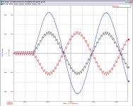
I have attached pdf and .ckt file of the schematic. Values are not optimized, I seriously suggest anyone interested takes a look at the aforementioned Putzey's and Karsten's patent applications.
First opamp is modeled with 1E5 gain and 100Hz dominant pole (a rather fast one, maybe it can be slower). Following is comparator with 20mV hysteresis (probably not necessary) and then delay block to mimic driver delay. I have deliberately chosen 150ns delay in the upper branch and 200ns delay in the lower branch. Also please note that the output filter components have different values to take into account real circuit tolerances.
Best regards,
Jaka Racman
Attachments
Hi Ivan,
Well, from my expirience, perfect overshot compensation of switching amplifiers can be achieved by proper choice of feedback compensation capacitor. You can have perfectly damped square wave response regardless of output load value. Take a look at the following two examples:
http://www.diyaudio.com/forums/showthread.php?postid=213929#post213929
http://www.diyaudio.com/forums/showthread.php?postid=285103#post285103
I also tested this idea a few years ago in a carrier based switching amplifier. It works like simulation predicted, but the main problem is noise increase because of coupling switching transient oscillations back to pwm comparator input and consequently increased jitter. But that is only an engineering problem.
BTW, this dampening of output filter is nothing new, it was already used in Carver hybrid amplifier (classic AB class with tracking switching power supplies). There are really few new things under this sun.
Best regards,
Jaka Racman
The third trick is input filter for overshooting compensation.
Well, from my expirience, perfect overshot compensation of switching amplifiers can be achieved by proper choice of feedback compensation capacitor. You can have perfectly damped square wave response regardless of output load value. Take a look at the following two examples:
http://www.diyaudio.com/forums/showthread.php?postid=213929#post213929
http://www.diyaudio.com/forums/showthread.php?postid=285103#post285103
I also tested this idea a few years ago in a carrier based switching amplifier. It works like simulation predicted, but the main problem is noise increase because of coupling switching transient oscillations back to pwm comparator input and consequently increased jitter. But that is only an engineering problem.
BTW, this dampening of output filter is nothing new, it was already used in Carver hybrid amplifier (classic AB class with tracking switching power supplies). There are really few new things under this sun.
Best regards,
Jaka Racman
- Status
- This old topic is closed. If you want to reopen this topic, contact a moderator using the "Report Post" button.
- Home
- Source & Line
- Digital Source
- Article on Philips prototype digital amp