50 buck infrared temperature scanner, and a steady hand ?
(or wack someone over the head, and steal his IR camera)
Sorry, got to run, still some tire rubber to sniff.
Someone once told me they used IR cameras while in the military.
They'd tell me why, but he said he'd have to kill me after.
I think he meant it.

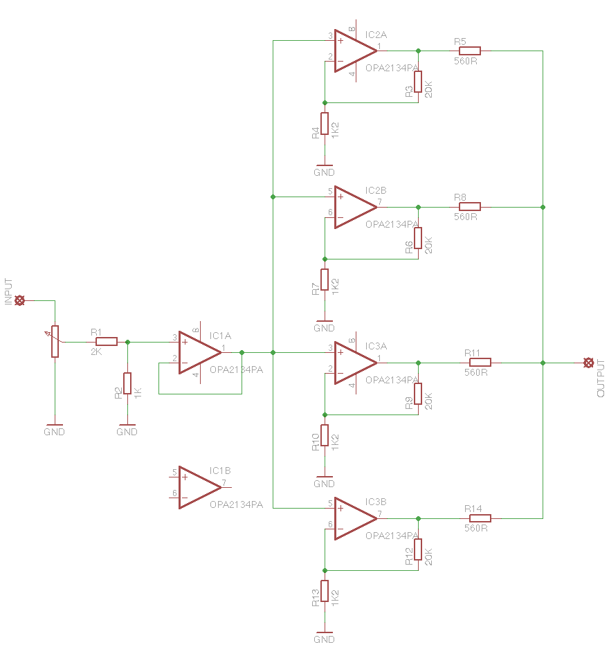
Here is a schematic I drew that has 4 op-amps in parallel. Each has a gain of 17.6 and an output resistor of 560ohms to limit the current. R1 and R2 are used at the front end to drop the voltage as the OPA2134 has in input voltage limit of +/- 0.7v. With a pk-pk input of 4v and the volume pot turned fully up, there is only +/- 0.66v at the input to the buffer.
Will this work? And if so, could I simply parallel a load more of the devices?
If this could work, maybe it could be 'The Beast with 100 Op-Amps'
Will this work? And if so, could I simply parallel a load more of the devices?
If this could work, maybe it could be 'The Beast with 100 Op-Amps'
Last edited:
The parallel combination of 100 opamps with 560 ohms in series with the output would give an output impedance of 5.6 ohms. The opamps have short circuit protection, they don't need that big of a resistor. The input offset is low enough that something like 10 ohms would work fine.
At an output of 20mA each opamp the output voltage can swing to about 2V from the rail. With 18V rails you have 16V peak, 2 A peak (20mA per) , that's 16W rms with 8 ohm load. Distortion raises quite a bit if you want too much gain or too much output current, especially at higher frequencies. Keep the output buffers at a gain of 1 or slightly higher. There is probably a better part out there.
I didn't try to figure out which package is best, probably the dual in 8 pin DIP.
Data sheet: http://www.ti.com/lit/ds/symlink/opa134.pdf
I didn't try to figure out which package is best, probably the dual in 8 pin DIP.
Data sheet: http://www.ti.com/lit/ds/symlink/opa134.pdf
isn't place for damn 8-legged bugs in some other thread ?

Then we are at least two who believes so!
OK. I have now posted my question and schematic here:
http://www.diyaudio.com/forums/chip-amps/228450-opamp-power-amp-would-work.html#post3338443
http://www.diyaudio.com/forums/chip-amps/228450-opamp-power-amp-would-work.html#post3338443
It takes debuger !!!isn't place for damn 8-legged bugs in some other thread ?
OK. I have now posted my question and schematic here:
http://www.diyaudio.com/forums/chip-amps/228450-opamp-power-amp-would-work.html#post3338443
Maybe you want to see what Douglas Self has done with this.
Maybe Large Scale Integrate [LSI] this Beast
The meticulously hand-wired prototype Beast worked with impeccable performance. The ongoing interest by DIYers worldwide may drive demand for the handmade and LSI Beast versions. The LSI Beast may have a lower cost than hand made.
Best regards.
This Beast may lend itself to LSI on a Si and/or a SiC wafer. Afterall, each individual P and N channel FETs belonged to a field of hundreds or thousands simultaneously made on a wafer by TOSHIBA or other. There is a precedence with CMOS Hex Inverters. Ditto for OP Amps which are also made by the tens or hundreds on a single wafer. Just link'em up.Maybe you want to see what Douglas Self has done with this.
The meticulously hand-wired prototype Beast worked with impeccable performance. The ongoing interest by DIYers worldwide may drive demand for the handmade and LSI Beast versions. The LSI Beast may have a lower cost than hand made.
Best regards.
Blues: Please direct me to the post of your speculation.Like I speculated before, I think Mr. Pass put together these little monsters to characterize it as a whole and reference it for his Pass SITs production...
- Status
- This old topic is closed. If you want to reopen this topic, contact a moderator using the "Report Post" button.
- Home
- Amplifiers
- Pass Labs
- Article: Beast With a Thousand Jfets