Looking at that picture a bit more, you could make the throat 'plate' whatever you want to call it able to have printed phase plug/adapters swapped out easily enough. Printers that can print that size of a piece, likely in 2 pieces are relatively inexpensive. ie: ~$300-350 USD (~$456 AUD).
I think I would make the throat easily replaceable [...] Make it modular
Do you mean like the joins / modularity used in WE15A ?
This is a very reasonable suggestion. If I don't do it that way, it will be because I'm too lazy to add the extra complexity - not because it is a bad idea.
Sort of like the adapter from a compression driver to a horn, but for a larger paper cone driver. Make the 'adapter' so that you can swap them out, or even just swap out phase plug inserts to test them.
The pictures I attached aren't terribly helpful, Im having a hard time finding a good pic of what I mean.
The pictures I attached aren't terribly helpful, Im having a hard time finding a good pic of what I mean.
Attachments
In the absence of any tips regarding throat & phase plug, I think I'll build the throat in a way that keeps my options open.
A primer: Phase Plugs
pics: https://www.google.com/search?q=hor...SAhVBfiYKHdf6COMQsAQIJg#imgrc=O2UvRSDeyCv91M:
GM
A primer: Phase Plugs
I like that page. However, it is purely focused on extending bandwidth, and doesn't answer my earlier question:
My rough prototype gives enough bandwidth.
If I don't need to improve bandwidth, is there any point in using a phase plug? That is: would a square(ish) throat + a phase plug be clearer / have better sound quality, or should I just do another slot throat?
OK, Haven't followed the thread, just noticed your remark.
If HR's response, polar plots are acceptable to you, and just as important, the CR is < 2:1 and preferably 1:1, then no; but, the XO point/slope comes into play and why often a phase plug is required to get the necessary 'flat' response through the XO BW for it to sum smoothly [Art's 'clarity' or at least mine].
GM
If HR's response, polar plots are acceptable to you
I learned something today - I was not aware that HR did polars.
HR says that at 500Hz, the -3dB 'beam' of the midbass horn I'm constructing will go to 15degrees off axis. That seems like enough. At a close listening distance (4m), a 30degree 'beam' will cover a sweet spot 2m wide, which is enough to cover a few seats.
In practice, the sweet spot should be a little more - HR assumes symmetry. With a 10x20 throat, I should get slightly more horizontal (and less vertical) coverage than it predicts.
Can you explain how that would help? When I simulate it, a ratio around 1:3 gives the best looking response plot. A 1:1 ratio gives a 5dB suckout ~75Hz.just as important, the CR is < 2:1 and preferably 1:1
HR predicts a similarly wide 'beam' at 500Hz.
That makes sense. I should have got a better (outdoor) FR plot. The one in post 29 is full of room artifact.but, the XO point/slope comes into play and why often a phase plug is required to get the necessary 'flat' response through the XO BW for it to sum smoothly [Art's 'clarity' or at least mine].
GM
Subjectively, it was good with a low order crossover, so is promising in that regard. I was too lazy to set up the DSP, so I used 1st order passive crossover + eq at the source (PC) to get ~flat output. The result was surprisingly easy to like.
Slow progress, I'm less far along than I hoped.
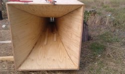
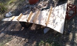
The internal pic shows how I'm forming the majority of the shape - by pressing the slightly bendy 7mm ply up against framing.
The external/mouth pic shows the framing for the last part of the expansion. There's a lot of tension in this part of the curve, so it helps to have a lot of surface area to glue & screw.
The brace that's at the bottom of the picture also helps to hold the mouth square. With hindsight: it would have been good to add these right at the beginning. They would have helped square up the outer shell, and thus made the whole job easier.
Attachments
Looks like damn fine progress!
You can kerf the inside of that 7mm plywood to get it to bend to the curve easier, set your circular saw to 2-3mm of cut, and cut some vertical 'kerfs' out.
It may not be all that necessary, 7mm is pretty thin. I would think it bends easily enough.
When all else fails, use a bigger hammer.
You can kerf the inside of that 7mm plywood to get it to bend to the curve easier, set your circular saw to 2-3mm of cut, and cut some vertical 'kerfs' out.
It may not be all that necessary, 7mm is pretty thin. I would think it bends easily enough.
When all else fails, use a bigger hammer.
You can kerf the inside of that 7mm plywood to get it to bend to the curve easier, set your circular saw to 2-3mm of cut, and cut some vertical 'kerfs' out.
I'm kerf-phobic. Rather than cut up thick ply (and deal with the constant roar of power tools), I prefer to reinforce thinner ply. That's what I did here. The side curves have a couple of vertical strips of hardwood affixed, to keep the ply stiff and straight in that dimension.
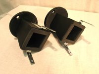
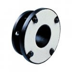
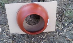
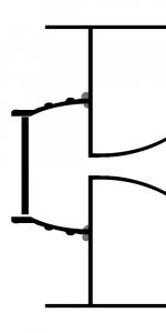
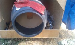
Pictured here is the prototype's rear chamber & throat plate. The prototype required an irritating, multi-part assembly, since the drum's lid was too small to load the 12" through. I've acquired better drums since then (bigger lids), so the horns I'm building now will be simpler and easier to weatherproof - they won't need a mounting plate, so I'll be able to glue the drum sections directly onto the rear of the horn. Attached is a diagram of how that will be set up.
These food drums are excellent components for the purpose: Easy to cut and glue, light, weatherproof. They seal airtight, but give good driver access.
On the topic of weatherproofing: a quick trial shows the fibreglass bugscreen laminates onto ply with no fuss at all, so I got a full 50m roll. It's cheap in bulk.
Attachments
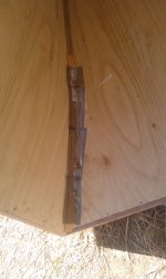
This is my version of kerfing. The reinforcing timber is all salvage / scrap.
Despite my disorganisation & this being an occasional / weekend project, the horn is actually approaching completion.
Next steps:
Get those corners finished (airtight)
Mount the driver plate & rear chamber
Test and tweak
Get the surface finished / waterproof before winter
The throat is currently 10x20cm. My intent is to try with / without a simple phase plug.
Attachments
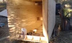
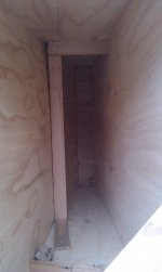
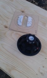
This is the driver plate & rear chamber, with the bottom half of the throat on view. The opening is easily big enough to load the 12" driver through it. It should be reasonably rigid, and airtight, when the lid is screwed on.
The gap on either side is <30cm, I have to be a bit nimble to access the horn interior.
Eventually, I'll add a lot of bracing to this chamber, and experiment with reducing the volume ...but this can wait until I'm sure I'll never have to flip the horn again. In the short term, I'm wary of adding too much extra weight.
The second pic shows how I'm getting the corners strong & airtight: lots of timber+glue, then a layer of mesh over that, which I'll fill in with bulk glue. There's no practical benefit to getting them this smooth - I think I just want them to look pretty once they are painted.
Attachments
Last edited:
This is the driver plate & rear chamber, with the bottom half of the throat on view. The opening is easily big enough to load the 12" driver through it. It should be reasonably rigid, and airtight, when the lid is screwed on.
The gap on either side is <30cm, I have to be a bit nimble to access the horn interior.
Eventually, I'll add a lot of bracing to this chamber, and experiment with reducing the volume ...but this can wait until I'm sure I'll never have to flip the horn again. In the short term, I'm wary of adding too much extra weight.
The second pic shows how I'm getting the corners strong & airtight: lots of timber+glue, then a layer of mesh over that, which I'll fill in with bulk glue. There's no practical benefit to getting them this smooth - I think I just want them to look pretty once they are painted.
You might be able to use a polyester body filler, 'Bondo' is the common brand here in the USA. It's fairly easy to apply, sands easily, etc.
Bondo stinks as it cures, stinks like stinky stink. Also, if it gets on your skin while curing it can burn a little.
So, essentially I'm recommending a stinky, skin burning product to use.
Cheers. Working outdoors, I'm not too bothered by stink. The price is a bit high, though - Bondo is locally available at $27 for 400g.
Where I need bulk, I'm using a much cheaper construction adhesive - I get packs of 3x320g tubes for just $5.80 ('Parfix' brand). This means I can use a lot.
It is messy and does shrink slightly as it dries, but is strong, not brittle, and not very toxic. When I apply by 'hand', I wear elbow-length gloves.
Similarly, the high cost is why I'm not going to wrap the enclosure in a thick fiberglass shell.
Despite using of cheap and salvaged materials where I can, cost per enclosure will still be about > $600.
$400 timber (mostly: 8 sheets of ply)
$70 external glue (assuming I use 4 litres)
$60 fibreglass mesh (bug screen) ~15 metres
$30 external paint (assuming I use 4 litres)
$15 food drum (for rear enclosure)
+ miscellaneous (tarpaulin, screws, adhesive)
Got it finished enough to fire it up, play some music (which was good), and take some rough measurements.
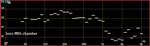
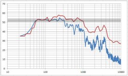
The chunky image is from my phone - the (Audio Tool app) 6 bar per octave view. This is using the wee Dayton mic.
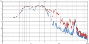
The more detailed graph is plotted from the AT files:
blue = open rear chamber & minidsp 400Hz lowpass filter (the spike at 4kHz is ambient noise: cicadas).
red = closed rear chamber, no filter.
I haven't yet got it airtight and fully braced. My chamber 'stuffing' was two old shirts. The throat is still a trifle oversized (on purpose, to allow for phase plug shenanigans).
It can only improve from here
The chunky image is from my phone - the (Audio Tool app) 6 bar per octave view. This is using the wee Dayton mic.
The more detailed graph is plotted from the AT files:
blue = open rear chamber & minidsp 400Hz lowpass filter (the spike at 4kHz is ambient noise: cicadas).
red = closed rear chamber, no filter.
I haven't yet got it airtight and fully braced. My chamber 'stuffing' was two old shirts. The throat is still a trifle oversized (on purpose, to allow for phase plug shenanigans).
It can only improve from here
Attachments

Near perfect 2 octaves
I communicated poorly: these were pink noise tests. So it is more extended but not as smooth as that graph suggests.
In Audio Tool, pink noise displays as flat in the bar graphs, (1/1, 1/3 and 1/6 octave views). For the detailed graph, I should have switched to white noise, or applied a 3dB/octave correction in the spreadsheet.
Here is the info again: pink noise, rear chamber on, with the 1/6 octave & full detail plotted together.
Attachments
- Status
- This old topic is closed. If you want to reopen this topic, contact a moderator using the "Report Post" button.
- Home
- Loudspeakers
- Multi-Way
- Artichoke Horn