Hi Everyone,
Thanks for all the help, including, of course, ernperkins who was the first to spot it.
I completely agree with everyone who says my plots don't look right. I'll upload the raw data in a little while, but I want to keep an open mind as to what "right" should be, and if I'm totally wrong would like to prove myself wrong via experimentation. Here's how I ended up "leaving the reservation":
When we evaluate a measurement technique we usually do so with the idea that far-field is messy, but king. The reason for the esteemed Mr. Bagby's blender and baffle step modifications to the near-field are to match up one to the other. And many have proven this works reliably. Myself included, though I may not bother at times.")
We assume that all of the wiggles below that are room issues. Here's my cognitive dissonance. I've never seen a real ported speaker end up measuring in the far field like the textbooks, at or below port resonance. ernperkin's plots are an example of the current state-of-the-art technieques. I would love help being guided back to the land of reason and physics.
So it boils down to this: I did something different and it is matching up far better to the far-field. Help me come to grips, please.
Best,
E
Thanks for all the help, including, of course, ernperkins who was the first to spot it.
I completely agree with everyone who says my plots don't look right. I'll upload the raw data in a little while, but I want to keep an open mind as to what "right" should be, and if I'm totally wrong would like to prove myself wrong via experimentation. Here's how I ended up "leaving the reservation":
When we evaluate a measurement technique we usually do so with the idea that far-field is messy, but king. The reason for the esteemed Mr. Bagby's blender and baffle step modifications to the near-field are to match up one to the other. And many have proven this works reliably. Myself included, though I may not bother at times.
We assume that all of the wiggles below that are room issues. Here's my cognitive dissonance. I've never seen a real ported speaker end up measuring in the far field like the textbooks, at or below port resonance. ernperkin's plots are an example of the current state-of-the-art technieques. I would love help being guided back to the land of reason and physics.
So it boils down to this: I did something different and it is matching up far better to the far-field. Help me come to grips, please.
Best,
E
Last edited:
Here are my raw data files.
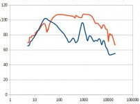
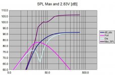
I calculated the port contributions using XSim. I treated the port and driver as speakers, adjusting polarity, distance and level of the port until it matched the far-field measurements. Total cheat, and the phase angles never matched, but amplitude did, nearly exactly.
I calculated the port contributions using XSim. I treated the port and driver as speakers, adjusting polarity, distance and level of the port until it matched the far-field measurements. Total cheat, and the phase angles never matched, but amplitude did, nearly exactly.
Attachments
The easiest way to splice is to match woofer and port level at a point far enough below port tuning. Hard to do with yours. Look at keele's nearfield paper and you will find scaling factors based on area, but I suspect that won't work for these files because it is a vector sum and your measured phase looks strange, and your files don't have the same frequency resolution and the levels are very far apart, like 108dB or so....
I did a little vlookup magic and came up with this - your match before the vector sum should look something like this (probably +/- 3-5dB or so).
I did a little vlookup magic and came up with this - your match before the vector sum should look something like this (probably +/- 3-5dB or so).
Attachments
- Status
- This old topic is closed. If you want to reopen this topic, contact a moderator using the "Report Post" button.
- Home
- Loudspeakers
- Multi-Way
- Art of FR Splicing: SS 18W/4531