The resonance isn't showing up as a resonance. You'd see something like that in several respects, and I'm not seeing it. (..though there might be a quality control problem among drivers.) CSD looks clean as well:
http://www.lightsoundjournal.com/images/2008/tpl4.jpg
The "tilt" is there for getting good vertical dispersion out of a design like this over a range of listening distances from the loudspeaker. Basically lower the tweeter height and "aim" up to the length of the line. At your position the line is a point source and at 1.5 kHz cut-off and because of the "tilt" there is added pressure loss higher in freq.s - all of which makes it a moot point.
Note: all of this is pretty easy to try for yourself with dsp. I would recommend trying all of these basic designs with some cheap drivers for your line and an inexpensive solid-state amp(s). (..and some cheap plywood or even cardboard.) It should give you a good idea where you'll want to head with your final design. (..if you hear a tweeter resonance, where you like your line low-passed, etc..) BTW, with my array experiments I did like the back-ward tilt on almost *all* designs (..including a full array line).
-it's Brandon's (Augerpro's) website (..very nicely providing the data to others).
Was wondering about the MMMMMMTWW. Assuming the midrange array is 100cm long, would c-t-c to the 22cm tweeter be 50+11=61cm? Based on above post by nc535.
Assuming a line of 3 or 4 midranges above the tweeter provide enough gain, what would be the benefit of using an array of 6 midranges if at the listening point both alternatives behave as point sources. An honest question rather than a challenge.
c-t-c spacing is irrelevant at 1.5 kHz with a very steep crossover and a MMMT design as spec'ed (..an angled tweeter upward also aids in this at increasing distances from the loudspeaker).
-remember, this isn't a split line like an MTM. The Heil-type driver is radiating at its lowest freq.s right near the top of it's surface. The mid has a similar result where 1.5 kHz is a wavelength larger than the surface of the driver (..assuming a mid like the 18 sound driver or smaller).
To me, most MTM's don't sound right w/ exceptions always depending on how low the freq. was for the high-pass filter. The lower in freq. for the tweeter, the better the subjective result (..though you can have problems with hearing the mid's signature vs. that provided by the tweeter - typically from a very steep crossover. Note that this is always a problem with steeper crossovers, though with dsp you have a lot of flexibility and a standard filter isn't necessary.)
Other than gain there isn't a huge difference. It is however usually better to go series parallel for gain and a load that's reasonable for the amplifier (4, 6, or 8 drivers). Finally, there can be a subjective difference with an extended array that provides an "image" that's taller. This happens more as the array's freq.s response extends higher, but even at 1.5 kHz it still adds to this impression.
Last edited:
MTM is just fashion. I'ts a flawed concept that will have poor of axis frequency response and when those reflections meet the direct sound - well.... Its technically broken out of the box really and no speaker using it will be truly good. My take. A proper long array is something else all togheter.
//
//
How do I run the math for beam width of two woofers side by side running the same frequencies?
Good point! Thanks
Definitely an option. B&C 8PE21.
You would be surprised. 4FE35 has very nice extension: flat 300 to 5500Hz. Nice. Sensitivity at 91dB is a little low for my needs, and the dispersion pattern of such a small woofer is of concern. That is why I asked about the math to understand beam width side by side.
Midbass: Beyma 10G40. Can easily go up to 1kHz, but not their strength of course.
math for two drivers??? Simulation, not math. You can use XDIR for a quick look and something like Jeff Bagby's Passive Crossover Designer for higher accuracy. Just model an MTM with the tweeter level way down.
math for two drivers??? Simulation, not math. You can use XDIR for a quick look and something like Jeff Bagby's Passive Crossover Designer for higher accuracy. Just model an MTM with the tweeter level way down.
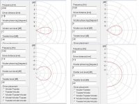
Got you. Playing with xDir it seems if I choose MTM and set driver distance to 100mm and set the tweeter very low in gain, then the M-M distance is 200mm. So I opted for MMT and used a midrange to midrange distance of 110mm to simulate the horizontal dispersion of a vertical array built with two 4" drivers side by side almost edge to edge. So an array of maybe 4V x 2H, or 3V x 2H. Below is the simulation at 500Hz, 1, 1.5 and 2kHz.
What should be my interpretation of this? I'm thinking at 2kHz dispersion is 60 degrees, at 1.5k it's about 70-80 degrees, and at 1kHz it's close to 180 degrees.
Hence if I insisted on using the horn in the TPL I could use a vertical array 2 drivers wide to get close to 80 degree horizontal dispersion at the xo point. Correct?
And if I decided to go without the horn I would be better off using a vertical array 1 driver wide to better match horizontal dispersion at the xo point. Correct?
Interesting stuff.
Attachments
;Got you. Playing with xDir it seems if I choose MTM and set driver distance to 100mm and set the tweeter very low in gain, then the M-M distance is 200mm. So I opted for MMT and used a midrange to midrange distance of 110mm to simulate the horizontal dispersion of a vertical array built with two 4" drivers side by side almost edge to edge. So an array of maybe 4V x 2H, or 3V x 2H. Below is the simulation at 500Hz, 1, 1.5 and 2kHz.
What should be my interpretation of this? I'm thinking at 2kHz dispersion is 60 degrees, at 1.5k it's about 70-80 degrees, and at 1kHz it's close to 180 degrees.
Hence if I insisted on using the horn in the TPL I could use a vertical array 2 drivers wide to get close to 80 degree horizontal dispersion at the xo point. Correct?
And if I decided to go without the horn I would be better off using a vertical array 1 driver wide to better match horizontal dispersion at the xo point. Correct?
Interesting stuff.
The journey is long; good thing we find it interesting.
Set the woofer level to 0 in XDIR then you can read the beamwidth off the graph as 2x the angle where the red line crosses the - 6db line. Make small changes in the driver distance to fine tune the beamwidth. I found that with 140 mm, I got about 80 degrees at 1300 Hz, which is where the TPL waveguide loses control, IIRC. If you space the drivers out too far or you will get lobing at HF, but this won't matter because of your low pass filter, so you can fine tune the directivity this way.
ScottG made a good point in his most recent post about directivity not mattering far enough away from XO. XDIR shows us increasing lobing at XO as driver to driver distance increases. But as we use ever steeper crossover filters, the frequency range over which these lobes occur gets smaller. If they get small enough, they become inaudible (psycho-acoustic filtering). If we used brickwall filters sound would switch instantaneously from one driver to the other as frequency rose and there would be no behavior at XO to worry about. Steep XO filters in DSP are the subject of other threads but they are how you deal with CTC great enough to cause lobing.
I agree that the 2 driver wide array is the way to match the horizontal directivity of the waveguide. I haven't thought about system design without the wavequide but its unlikely to require or benefit from a 2 driver wide array. To that extent I agree with you.
I assume that w/o the waveguide, the directivity will be entirely different and that the XO will need to move up since there is no longer any horn loading to support it at the low end. Sensitivity will be lower from lack of horn gain. Without the waveguide, you no longer have controlled directivity and so in room you will have more reflections to deal with. Such a move might be out of the frying pan and into the fire. You will get a smaller CTC but there will be other issues to deal with.
;
The journey is long; good thing we find it interesting.
Set the woofer level to 0 in XDIR then you can read the beamwidth off the graph as 2x the angle where the red line crosses the - 6db line. Make small changes in the driver distance to fine tune the beamwidth. I found that with 140 mm, I got about 80 degrees at 1300 Hz, which is where the TPL waveguide loses control, IIRC. If you space the drivers out too far or you will get lobing at HF, but this won't matter because of your low pass filter, so you can fine tune the directivity this way.
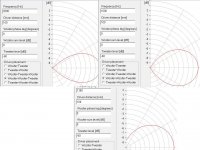
Thanks for telling me how to read it. A new run, now at 100mm woofer c-t-c (4FE35 edge to edge).
At 2kHz the -6dB is about 70 degrees. Maybe a bit more. Probably close enough to the TPL horn 80 degree.
Lowering XO to 1.6kHz would be on the safe side in terms of horizontal dispersion match to the horn. By 1.8kHz it's somewhere 80 to 90 degree at -6dB.
So going down this path I envision an MTWW, with the TPL using the horn and where the M represents and array of 2-wide by 3 or 4-high 4FE35. Not saying I'm sold on this design, but horizontal dispersion control would be the benefit of an array of 2-wide.
What are the downsides of this path?
Attachments
I hate side-by-side drivers at upper mid. to high freq.s (..it can work out really nice around 500 Hz though). Imaging is crap when you do it well over 1 kHz (in my experience).
If you absolutely *must* use the horn, make a matching short horn for the mid array with appropriate baffle.
-still, if you've got the drivers then you can always try both (..and who knows, you might like the result of side-by-side up to 1.6 kHz).
If you absolutely *must* use the horn, make a matching short horn for the mid array with appropriate baffle.
-still, if you've got the drivers then you can always try both (..and who knows, you might like the result of side-by-side up to 1.6 kHz).
Thanks for telling me how to read it. A new run, now at 100mm woofer c-t-c (4FE35 edge to edge).
At 2kHz the -6dB is about 70 degrees. Maybe a bit more. Probably close enough to the TPL horn 80 degree.
Lowering XO to 1.6kHz would be on the safe side in terms of horizontal dispersion match to the horn. By 1.8kHz it's somewhere 80 to 90 degree at -6dB.
So going down this path I envision an MTWW, with the TPL using the horn and where the M represents and array of 2-wide by 3 or 4-high 4FE35. Not saying I'm sold on this design, but horizontal dispersion control would be the benefit of an array of 2-wide.
What are the downsides of this path?
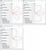
Yes, side by side 4" drivers can get you a horizontal directivity match but so can single wide 8" drivers.
The vertical center to center distance from the 3 or 4 high array of side by side 4FE35's is measured from the vertical midpoint of that array so its going to be greater than for 8" mids, if, as you implied, the array of mids is above the T. This will give you pretty severe lobing, as shown below for 3x2 MT.
These lobes are at angles where they can reflect down to the LP and perturb the frequency and phase response, perhaps even causing nulls. But if you have floor and ceiling treatment you may be able to ignore them.
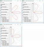
You would get less lobing using MTMWW or WMTMW with the 8PE21's as M. The center to center distance with this is less than the tall array of 4FE35's and should also have a good horizontal directivity match. You should use steep XO filters to minimize lobing effects and as low an XO frequency as you can get without hearing strain on the T.
Here is the XDIR vertical directivity for MTM with 8" mids at 2000, 1600, and 1300 Hz XO.
The MTM with 8" drivers is only marginally better until we get down to the 1300 Hz crossover. There the lobes are narrower and point more directly at floor and ceiling where it will be easier to absorb them or keep them away from our ears.
Attachments
Sooner or later I was doomed to reaching here...not knowing where to go next ")
I don't have the midrange drivers so would need to buy to run tests. My options, as I think about them now:
8PE21: either TMWW, or MTMWW. I've seen before comments leading to conclude MTM with this tweeter and 8" midranges would yield severe lobbing. Plus several comments here saying MTM is not good. Still Achenbach has a speaker with good reviews, this tweeter and 8" midranges. Also tough to see a xo at 2kHz with this driver. TMWW is an option, but rather shy sensitivity for my needs.
6ND410: MTMWW or MMMMTWW, where same comments as above apply to MTM. This driver has good frequency response, great sensitivity, horizontal dispersion close to 80 degrees at 1.8-2kHz. Le is a bit high though.
On post #62 ScottG said
6FE35: this looks like a great driver with great frequency response and low Le, but I need several to reach enough sensitivity and cone area, and too wide dispersion at 2kHz given the small size. Either a vertical array 1-wide at the side of the tweeter without the horn (like Nola), or a vertical array 2-wide to match horn dispersion.
ScottG states in his experience 2-wide in my midrange range kills imaging (something I value). Bummer.
As nc535 mentioned earlier, taking the horn off the tweeter and using the 4" mids would make dispersion very wide.
So if I'm understanding all this well, and if indeed as I understand ScottG said the c-t-c between the center of a MMMM and the T is not a problem, it seems 6ND410 would be the way for me to go. Bummer as 4FE35 is so much cheaper
I don't have the midrange drivers so would need to buy to run tests. My options, as I think about them now:
8PE21: either TMWW, or MTMWW. I've seen before comments leading to conclude MTM with this tweeter and 8" midranges would yield severe lobbing. Plus several comments here saying MTM is not good. Still Achenbach has a speaker with good reviews, this tweeter and 8" midranges. Also tough to see a xo at 2kHz with this driver. TMWW is an option, but rather shy sensitivity for my needs.
6ND410: MTMWW or MMMMTWW, where same comments as above apply to MTM. This driver has good frequency response, great sensitivity, horizontal dispersion close to 80 degrees at 1.8-2kHz. Le is a bit high though.
On post #62 ScottG said
Suggesting the distance from the center of the MMM to the T would not be of concern regarding lobbing. Yet nc535 sees it otherwise. Sorry, don't mean to create conflict, but these are conflicting points of views, or maybe I'm misunderstanding.c-t-c spacing is irrelevant at 1.5 kHz with a very steep crossover and a MMMT design as spec'ed (..an angled tweeter upward also aids in this at increasing distances from the loudspeaker).
6FE35: this looks like a great driver with great frequency response and low Le, but I need several to reach enough sensitivity and cone area, and too wide dispersion at 2kHz given the small size. Either a vertical array 1-wide at the side of the tweeter without the horn (like Nola), or a vertical array 2-wide to match horn dispersion.
ScottG states in his experience 2-wide in my midrange range kills imaging (something I value). Bummer.
As nc535 mentioned earlier, taking the horn off the tweeter and using the 4" mids would make dispersion very wide.
So if I'm understanding all this well, and if indeed as I understand ScottG said the c-t-c between the center of a MMMM and the T is not a problem, it seems 6ND410 would be the way for me to go. Bummer as 4FE35 is so much cheaper
Note that you can get the frame of each driver (non-horn TPL-150) and 6ND410 within about 15mm's from the emitting surface area at 1.5 kHz for each driver.
-that's only a 30 to 40 mm difference between driver's (with some "gap" between frames for each).
Note that you can go the 4FE35 "route", but you won't get the gain you need IF you go with a narrow baffle. (..but you might not need it if you go with a more powerful amp.)
Both drivers would require a NON-horn dispersion for matching at lower freq.s. assuming a standard vertical only configuration. (..rather than side-by-side.)
Finally, It only takes 2 mid. drivers to test the side-by-side method, and the drivers don't have to be expensive - just the same 4" diameters as the Faital Pro drivers if those are what you are interested in. Partsexpress in the US has such drivers for less than $10 each, and I'm betting that sources in Europe have something similar. Remember, your experience may be favorable.
8 of these might be interesting for not a lot of money (and 2 could be your starting-point to see if you like side-by-side and also if you like these particular drivers):
Driver Detail | Tymphany
This has been an interesting and challenging exercise - to see if all of your constraints can be met in accordance with good design principles. Now its apparent that something has to give.
If you use DSP for XO with steep filters, then CTC becomes more or less irrelevant and other topologies, including TMMMM should work. DSP may be more digital than you like and implies line level XO and thus two amps, one for T and one for the M's. Passive XO gets more complicated and expensive with steep filters and you might lose efficiency in losses in the XO. But if you are comfortable with DSP and 2 amps, I would say go this way.
There is another issue easily solved with DSP and not so easily passively - time alignment. The T in the TPL will be behind the mids by the depth of its horn, less the depth of the mid cone, less differential delay in XO filters. Stepped or tilted baffle helps but you may need some additional delay.
If you had a more powerful amp or would/could use two of them, then the quad 4FE35 MTM solution gets close enough on CTC and a 2nd amp makes up 3 of the 4 db difference in sensitivity compared to a dual 8" MTM. This is still passive XO territory. It might be the simplest solution.
I may have discouraged using the TPL w/o its horn more than I meant to. I meant to say more that its a different design with different issues than it would necessarily lead to an inferior system solution. Getting the horn out of the way makes meeting CTC easier and keeps you in passive XO territory. What about the lower directionality? In a large enough room far enough from the front and side walls, the reflections from the walls will be delayed enough to improve the sound. In a small room the reflections arrive at the ears too soon and thus first reflection points need to be treated. So the solution without a horn might work well for you.
Pick the one that works in your room. See it from your listening seat. If you can fight first reflections and only care about a single listening height a wmmtmmw might make sense.
The multiple mids will help fight anything except vertical planes.
Be aware where the biggest reflections skew your results. (Floor / ceiling) Most likely in the lower mids. Multiple drivers there can average out the largest problems. Find the solution most likely to work with your room. I like the proposition to ditch the horn. To pack the mids closer together, just view it from a listener's perspective. Once you get past 2 drivers, center to center distance isn't the only goal. Look at driver to ear distance at the listener's position. Every listener position you regard as being important.
Center to center distances only varies the vertical performance.
At a single height even wmmtmmw would mean total symetry in the wave front. ( or even more 'w's if needed)
INTERESTING DISCUSSION....
This discussion is interesting..
I have a 24db electronically crossed tri-amped line array, with Per channel: 16 3.5 inch mids, 32-3/4 dome tweeters, and one 12 inch long throw Dual voice coil woofer.
But I retired and moved from my previous house with its dedicated music room. My wife took over the TV room where the line array is, and watches TV all the time there. And so I am listening downstairs in the living room(big open concept liv/din/kit 24 x 24). But no Line arrays allowed there due to the WAF.
So I am building a new set of 4 way, electronically crossed, quad amped speakers. Per side: 1 -12 inch woofer, 1 -8 inch mid woofer, 4 -3.5 inch mids, and 4 -3/4 soft dome tweeters.
The mids are specifically 3.5 inchers (Tympany's flat Freq response low distortion to begin with) because comb filter distortion starts at 1130/highest frequency of the speaker before cross times 12. Since I want the mid ranges to cover 300-3000, they have to be no more than 4.52 inches center to center(see James Griffin, PhD, White paper on line arrays). Effectively placed in a square each with a separate tube enclosure, they are kind of like a Point Source Array, with the benefits of lowered distortion, higher sensitivity, and high power handling, but no nearfield experience.
The tweeters can only be Dayton ND20F's because I have to cut the flanges on two sides to get them within .84 inches center to center, to avoid comb filter distortion below 16000 hz. Since I cannot hear much above that, any comb distortion will be inaudible to me. Same benefits as the mids.
I will miss the nearfield experience, but the WAF prevents the speakers from rising more 43 inches from the floor.
Both drivers would require a NON-horn dispersion for matching at lower freq.s. assuming a standard vertical only configuration. (..rather than side-by-side.)
Why do you say this? Per my calculations, a 6" woofer has an effective diameter of about 5.3", which at 2kHz has a dispersion of about 1000000/(5.3x2000)=95 degrees which doesn't seem that far from 80 degree horizontal dispersion for the TPL horn. Not a challenge, but rather seeking to truly understand.
cheers
If you use DSP for XO with steep filters, then CTC becomes more or less irrelevant and other topologies, including TMMMM should work. DSP may be more digital than you like and implies line level XO and thus two amps, one for T and one for the M's. ... But if you are comfortable with DSP and 2 amps, I would say go this way.
There is another issue easily solved with DSP and not so easily passively - time alignment.
In a large enough room far enough from the front and side walls, the reflections from the walls will be delayed enough to improve the sound. In a small room the reflections arrive at the ears too soon and thus first reflection points need to be treated. So the solution without a horn might work well for you.
To clarify: I am definitely using digital crossovers, time-aligned, room-corrected, steep filters. Certainly one amp for tweeters and another for mids, and another for midbass and another for subwoofer. And I want the tweeter and midrange amps to be SETs, so efficiency is of importance...which leads to me trying to keep the horn on the TPL.
My room is not big: 4.5 x 5 x 2.4 meters.
Why do you say this? Per my calculations, a 6" woofer has an effective diameter of about 5.3", which at 2kHz has a dispersion of about 1000000/(5.3x2000)=95 degrees which doesn't seem that far from 80 degree horizontal dispersion for the TPL horn. Not a challenge, but rather seeking to truly understand.
cheers
TPL 150-H at 2kHz is about -6db at 40 degrees, where the 6ND410 is -2db. (..looking at actual measurements.)
On top of that, there is the dependence on diffraction elements for both drivers relative to the baffle. Narrow baffles tend to diffraction gain around the width of the baffle as it relates to wavelength. That diffraction can have the effect of making the result LESS directive.
Say a baffle of 8" with a wavelength around 1700 Hz, along with a crossover at 2 khz, and a steep cutoff for each high and low pass filter.
The result then would be very non-directive up to 2 kHz, and then a serious drop in pressure more than 15 degrees off-axis as freq.s increase.
In other words:
-it would be bad (if you value uniformity off-axis), VERY BAD.
As an alternative with the same drivers: consider a larger baffle of at least 14" width, a crossover around 2.5-2.7 kHz, and a crossover that is MUCH less "steep".
Last edited:


- Status
- This old topic is closed. If you want to reopen this topic, contact a moderator using the "Report Post" button.
- Home
- Loudspeakers
- Multi-Way
- Array for midrange: good idea?