Allright, admittedly a bit of a clickbait title as there was strictly no blood involved and the explosiveness of the power supply caps is only assumed at this stage - but I could really use some help over here since this is my first repair attempt.
I purchased this Armstrong 626 amplifier (S/N: 613377, seems to be a rather early series) yersteday from a guy whose brother-in-law, an audiophile collector, recently passed. When said guy plugged the amp without load after an undetermined amount of time without use it very briefly turned on before he heard a "schplat" and everything went dark.
According to what I have read from Jim Lesurf's excellent Armstrong part of his website, and Mike Solomon's Armstrong Repair shop's site it appears as though "The power supply capacitor can fail, spraying corrosive fluid onto a circuit board, causing massive damage."

I am leaning toward this lead since some wires appear to have suffered from corrosion that "ate" the plastic cover and exposed the metal shielding (or is it the wire?).


But I canno't grasp how the toroidal transformer can be that drenched in what seems to be an oily fluid seeing how little are the leaks from the power supply caps, and also the fact most of the wetted area seems to be directed toward the back of the unit where no capacitor are present?

Unfortunately I haven't figured out how to remove the plastic underside yet so I couldn't check what's happening backstage. It looks as though a sleeved cable is also drenched in fluid under what I beleive to be the speaker output capacitor (which has a visible tiny "leakage sprout" as well and reads 4.130 mF instead of 3300 uF, so surprisingly almost still within spec! If not accounting for spraying crap all over the place of course).

So my questions are: is it salvageable without having to replace the transformer? Is the fluid dangerous for the skin (cap reference: KA3174AGT 74, 100vDC / 3300 uF) and will it dry out eventually? Should I try to clean it or remove/replace the draping on the transformer?
My only tools are a digital multimeter and soldering iron, I have no audio-specific machinery. The fuse seen in the picture has current continuity, the damaged 47kOhms metal resistor is still perfectly on spec. Here are the schematics in case it could help.


I purchased this Armstrong 626 amplifier (S/N: 613377, seems to be a rather early series) yersteday from a guy whose brother-in-law, an audiophile collector, recently passed. When said guy plugged the amp without load after an undetermined amount of time without use it very briefly turned on before he heard a "schplat" and everything went dark.
According to what I have read from Jim Lesurf's excellent Armstrong part of his website, and Mike Solomon's Armstrong Repair shop's site it appears as though "The power supply capacitor can fail, spraying corrosive fluid onto a circuit board, causing massive damage."
I am leaning toward this lead since some wires appear to have suffered from corrosion that "ate" the plastic cover and exposed the metal shielding (or is it the wire?).
But I canno't grasp how the toroidal transformer can be that drenched in what seems to be an oily fluid seeing how little are the leaks from the power supply caps, and also the fact most of the wetted area seems to be directed toward the back of the unit where no capacitor are present?
Unfortunately I haven't figured out how to remove the plastic underside yet so I couldn't check what's happening backstage. It looks as though a sleeved cable is also drenched in fluid under what I beleive to be the speaker output capacitor (which has a visible tiny "leakage sprout" as well and reads 4.130 mF instead of 3300 uF, so surprisingly almost still within spec! If not accounting for spraying crap all over the place of course).
So my questions are: is it salvageable without having to replace the transformer? Is the fluid dangerous for the skin (cap reference: KA3174AGT 74, 100vDC / 3300 uF) and will it dry out eventually? Should I try to clean it or remove/replace the draping on the transformer?
My only tools are a digital multimeter and soldering iron, I have no audio-specific machinery. The fuse seen in the picture has current continuity, the damaged 47kOhms metal resistor is still perfectly on spec. Here are the schematics in case it could help.
Attachments
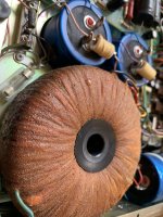
Does the transformer really feel that wet? I suspect it might have been factory impregnated with polyurethane or something like that which has degraded over the decades. Anyway, the brown blob at the capacitor that you've been showing in pic #2 indicates that this cap has dried out. Replace 'em all. Due to the lack of traces, I don't assume that any liquid has been spilled from this cap over the whole tranny.
The wire insulation damages most probably result from improper care during soldering.
Best regards!
The wire insulation damages most probably result from improper care during soldering.
Best regards!
This is probably late 1974 or early 1975-yes its an early one. I can confirm as per post 2 that the transformer is probably fine-they all look like that due to the coating. As in post 2 just replace the the 3 x large caps, you will probably find the smaller ITT Caps are all still within specI purchased this Armstrong 626 amplifier (S/N: 613377, seems to be a rather early series)
") .Looking at your pictures I see no evidence of leaking electrolyte apart from the crust on the 2 center caps. However if those caps are not changed soon they will eventually leak especially the smoothing cap located on the lefthand side.
.Looking at your pictures I see no evidence of leaking electrolyte apart from the crust on the 2 center caps. However if those caps are not changed soon they will eventually leak especially the smoothing cap located on the lefthand side.If you look along the rear edge of the base you will see 4 black plastic lugs with a slot. Just turn the lugs 90 deg and the Plastic base should come away from the body. Once that is removed check the mains switch and see if a has a 3 pin capacitor across it. If it has it will have probably failed causing a short across the mains. Remove the cap completely and then check all the fuses. Obviously you need to do this with the unit completely unplugged and isolated from the mains wall socket.
Good luck
Electrolytic cap slime is white, borax remains. Soluable in water. Not brown & oily. I'd wash off with a paper towel sprayed in 409/scrubbingbubbles/fantastik/spicnspaneveryday. Then water rinse on a towel. The borax can corrode metals like copper aluminum & steel. You can't wash off the corrosion. Good luck cleaning, and maybe later repairing.
If you look along the rear edge of the base you will see 4 black plastic lugs with a slot. Just turn the lugs 90 deg and the Plastic base should come away from the body. Once that is removed check the mains switch and see if a has a 3 pin capacitor across it. If it has it will have probably failed causing a short across the mains. Remove the cap completely and then check all the fuses. Obviously you need to do this with the unit completely unplugged and isolated from the mains wall socket.
Thanks for the tip! I have managed to remove the plastic base and indeed the 125mA fuse was blown. I have tried to pull the mains switch but it is resisting, took the 2 screws of the board out to see the other side of it and it looks like it is soldered on the other end - should I desolder it to see what's under the black main switch to look for that shorting 3 pins capacitor?
I have applied some paper-towel on it and indeed it isn't shiny because it is wet, but because of some sort of partially faded away plastic coating! Cheers, it's reassuring to know I don't have cancer-juice leaking from the transformer.Does the transformer really feel that wet? I suspect it might have been factory impregnated with polyurethane or something like that which has degraded over the decades. Anyway, the brown blob at the capacitor that you've been showing in pic #2 indicates that this cap has dried out. Replace 'em all. Due to the lack of traces, I don't assume that any liquid has been spilled from this cap over the whole tranny.
The wire insulation damages most probably result from improper care during soldering.
Best regards!
we may be at cross purposes here! The switch I refer to is the on/off switch which is located at the front left handside when you look at the unit from the top and front. With the base removed you should be able to see the live & Neutral cables connected to the on/off switch. Thats were the cap would be fitted if it has one. On later models this cap was not fitted.I have tried to pull the mains switch but it is resisting, took the 2 screws of the board out to see the other side of it and it looks like it is soldered on the other end - should I desolder it to see what's under the black main switch to look for that shorting 3 pins capacitor?
You’re a lifesaver: I saw the proper wires, confirmed no cap was present so proceeded to change the fuse and…Boom! In a good way! I had no speaker/source to try it on so I used the tuner, seems like it’s out of sync as I couldn’t get any fm station but noise, however I heard some talk over AM with a pair of headphones. what little I could hear was beautiful and warm, I’m very excited to hear more.we may be at cross purposes here! The switch I refer to is the on/off switch which is located at the front left handside when you look at the unit from the top and front. With the base removed you should be able to see the live & Neutral cables connected to the on/off switch. Thats were the cap would be fitted if it has one. On later models this cap was not fitted.
I’ve just ordered 3 new cans to replace the ouput capacitors and filter cap. You wouldn’t happen to have a parts list perchance? I have just realized the one I have found online was mislabeled as 626 but is in fact for earlier Armstrong series. I think I need to change some lightbulbs.
Unfortunately I dont have a parts list. I can confirm that the 3 xPilot bulbs are E5 12v 83mA and the 2 x tuning and signal strength wedge bulbs are 12volt 30mA. Both are available from RS.You wouldn’t happen to have a parts list perchance? I have just realized the one I have found online was mislabeled as 626 but is in fact for earlier Armstrong series. I think I need to change some lightbulbs.
RS Stock No.:655-9659
RS Stock No.:104-581
Hi, I've never posted to this forum, but have found it invaluable in trying to reincarnate my 625. I always liked the Armstrong range but was surprised at how badly it's put together - any decent wireman - or woman would disown mine at first glance under the lid.
I hope someone can help me, I've recapped the main 3 culprits, everything else looks ok, so I''ll leave well alone. My main problem is the 47 omh resistor which gets and stays hot, gently burning off what the years have deposited with a trailling whiff of smoke. Am I right in thinking this is the resistor that should be bypassed once the thermal delay switch operates? If so, where do I find the delay switch, is it repairable or replaceable? Any help would be very much appreciated.

I hope someone can help me, I've recapped the main 3 culprits, everything else looks ok, so I''ll leave well alone. My main problem is the 47 omh resistor which gets and stays hot, gently burning off what the years have deposited with a trailling whiff of smoke. Am I right in thinking this is the resistor that should be bypassed once the thermal delay switch operates? If so, where do I find the delay switch, is it repairable or replaceable? Any help would be very much appreciated.
Hi Trev, many thanks for your fast reply. I had wondered as some of the photographs I've viewed show no resistor. So this is a soft-start device, I'll have another poke around tomorrow.This combination of resistor and thermal relay was a later introduction in the manufacture of these amplifiers it helped to reduce switch on surge I used to bypass them without any problems
Trev
Again, thanks for the info.
Ted
I concur with post "11" by Trev. I also remove the soft start, although I was told by a an ex Armstrong tech that these were officially not included on the later models anyway. I have a 1979 model (639945) that does not have it fitted. They just had a solder tag connector in its place.
I did not just decide to remove the said thermal delay this was done after talking with an Armstrong engineer some 40 odd years ago
This and having seen earlier units without the device re-assured me that it would be ok
The best thing about this amplifier was the then innovative diode logic signal switching for the inputs
the super Vas design new for the time giving a low distortion
The radio section was also very good
Well done Ted Rule
Thank you all for invaluable advice, I've learned a lot from all the postings here. I have removed the thermal delay and beefed up the PSU diodes and all seems well. I'm in the process of replacing the blown E5 bulbs with warm white led equivalents. I may seem a daft point, but I've been struggling for ages with the spring type E5 bulb holders, which are very reluctant to give up what's left of the bulb. I eventually got one out, with the aid of heat and WD40, but the spring came off the base of the bulb holder and now seems impossible to put back. Should I cut my losses and just replace the bulb holders, or is there a trick?
Regarding the thermal delay unit, with a bit of fiddling you can slide the metal cover off. Inside is a heater, a bi metallic strip and some points which close as the strip is heated. I found that the points were dirty and so the switch didn't work so all the power was going through the resistor. I carefully cleaned the points and several years later it is still working. As others have said it isn't critical so there is nothing to lose by trying to repair it.
Another point I have discovered is that if you disturb the main amp board you are likely to move the wires connecting it to the pre amp. These need to be carefully run in the "well" between the two or they pick up hum. I replaced mine with coax leads and made them long enough to allow access to the back of the main amp board without disconnecting them.
Another point I have discovered is that if you disturb the main amp board you are likely to move the wires connecting it to the pre amp. These need to be carefully run in the "well" between the two or they pick up hum. I replaced mine with coax leads and made them long enough to allow access to the back of the main amp board without disconnecting them.
Many thanks for the valuabe information. i did what you suggested with the thermal delay unit and put it back into play. It seems to be working so I may leave it alone. The meters on my unit are severely stuffed. According to Mike Solomons, the heat from the lamps tended to fry the meters, and when pulling mine apart, they literally fell to pieces, so I can concur with that. I may just put them back together so they look ok, but I was wondering if I could rebuild them with new guts, cannabalised from available panel meters. Does anyone have any insight as to what they are and their values? It would be quite interesting to see if they could be restored to something like working meters.
- Home
- Amplifiers
- Solid State
- Armstrong 626, explosive capacitor, fire & blood