Hi,
Well, I finally got a tester. Everything okay, I left it set as it was from arjen's shop.
Got all the wireing and connections. Every thing ready to make first test and... BIIIIIIP!! this is the sound I get from the speakers. The I turned of and double check the connections and now is dead silence. I only hear the reles in the boards doieing double "click" when I swich on the amp, but nothing else...
Any idea or clue to start searching for the cause of this problem??
THANKS
No more TK2050 amps on arjen's ebay store!!!!!
Sold out? Hope he's making more.
Sold out? Hope he's making more.
I emailed Arjen and he said that the boards are out of stock - due to high demand. They will be back in pretty soon!
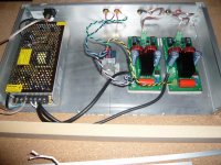
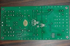
Here is picture from the amp with chassis. Just for testing. Connections supposed to be OK. Arjen has seen this picture also.
Still the amp turns on, or at least it makes the noise from the reles (like a quick double click) But no sound at all. Tested with my new fostex speakers also, and no sign. I've tried with out volume pot, strait connection from boards to RCA's, but nothing either.
I can tell that the "flat resistor" (on the right of PCB, between "little blue box, Heatsink and big cap) is really hot after a few minutes. Well, it gets hot early. Don't know if this means anything to you.
SMPS measures OK, it's set to 24V. I've tested with multimeter as recomended in previous thread.
Attachments
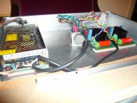
Juanito, can you post some closer pics? Would like to look at your volume pot wiring.
Also, set your new multimeter to VDC and with the amp on, place your probes on the two screws of the power connector on each board and let me know what you read. Just want to make sure you are not set to read AC on the multimeter.
If you are feeding the boards too much power (over voltage situation), the relays will click but there will be no sound coming at all.
Just thought of something, check the engagement of your wires with the connectors. Sometimes the wire goes in above the catch and when you tighten the screws, it is actually not grabbing the wire but is smashing down on the bottom detente, so you think you grabbed something, but in reality nothing. Pull on all the wires and see if they are secured or not.
Last edited:
Okay, I've tested the voltage and it's 24 in each board while on.
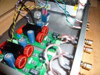
Here are the pictures, hope that you can see them well.
I tried the amp with out "chassis". So I hooked the loudspeaker cables strait to boards, and also I screwed spare RCA's out of the chassis, so there is no connection between them at all. RCA's are hanging out and PCB as well. Everything on top of a flat wood. Result: now one PCB makes a little pop to the speaker, but no sound at all. It moves the speaker out a little bit and it stays there, but noting else.
As source I use an ipod so I can control the volume.
I afraid I have to ship this PCB back.
Attachments
Hi all,
Been lurking on this thread...gonna get some of these when funds are available. Anyhow. Forgive me if all this stuff is obvious but may I suggest working with only one board at a time, no volume pot, and a different source than ipod -- a regular preamp or a dac or cd player with volume control. Ipods and other DAPs can be problematic in some instances. The goal is to have as few "new" components as possible in the test system.
-Michael
Last edited:
Hi all,
Been lurking on this thread...gonna get some of these when funds are available. Anyhow. Forgive me if all this stuff is obvious but may I suggest working with only one board at a time, no volume pot, and a different source than ipod -- a regular preamp or a dac or cd player with volume control. Ipods and other DAPs can be problematic in some instances. The goal is to have as few "new" components as possible in the test system.
-Michael
+1 agree, hard to believe both boards are toast.
Juanito,
Set your voltmeter to the 0-2 DC volt range, put the probes where the speakers would be, turn it on and see where this voltage goes. If this (DC offset) is too far off, it may keep the amp chip from coming on (not sure, been a bit since I read the datasheet). Anyways, the idea is to set this as close to 0 DC volts as possible using a small screwdriver and turning the little brass screw on the blue pot near the corner of the board. You will see the voltage move with the screw, at least when things are working that is.
A few more things to try before giving up.
thanks very much for your help! I'll try anything before giving up.

I don't think this will go better. I may have to ship back yo "china"!! And then back again... I'm not sure it's worth it. I would be better to sell as is and get a market amp like Rega or NAD or whatever deacent amp. Or try the other tk2050 boards.
I can't understand what has happened. I've done an amp from 0 with the worst solder in world an boxing, and it worked. I've done 2 ta2024's (sure and Arjen's), and fine. I've assembled a class A amp 50watt (my main amp), in a very similar way to this tk2050, and been fine for a few years, etc, etc.
I've tried everything you told me: thanks all of you for the great help and support!! Its really nice to see that this forum works.
Juanito

- Status
- This old topic is closed. If you want to reopen this topic, contact a moderator using the "Report Post" button.
- Home
- Amplifiers
- Class D
- Arjen Helder's 2050 boards