Hi all,
I've just received a faulty Alpha 9, and upon testing, I've found the following:
I'm able to use an Avo, have access to an oscilloscope, but don't know how to use it. How would I check if the tranny is dead? Does anyone know the voltages coming from the tranny?
Any suggestions as to what i could try would be brilliantly useful!
Dan
I've just received a faulty Alpha 9, and upon testing, I've found the following:
- Upon powering on, the display illuminates, allowing apparent track selection (no laser movement at all)
- There's a quiet high-pitched whining from the transformer/surrounding area
- The disc spins up and stops after a few seconds
- The laser does not move at all from the idle position at the outer edge of the disc.
- There is discolouration to the casing above the tranny, to the casing and the DAC mounting
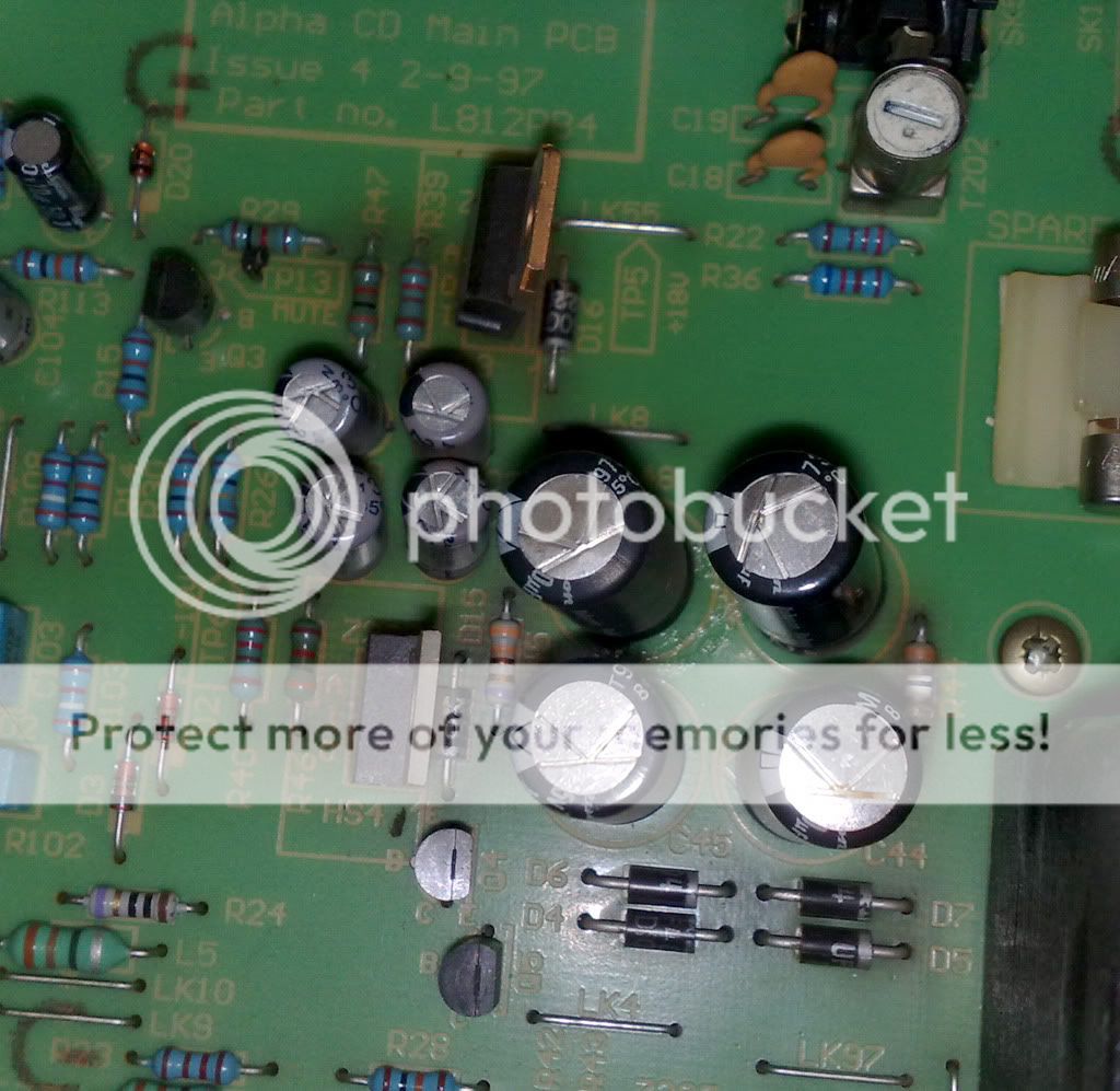
- The PCB around Z204 &205 is discoloured as pictured
- The metal part of Z207 is slightly discoloured
- Resistor R44 is a bit burnt. Inout 31V, output 5V
- Caps C44,4 & 48 sligthly bulging.
An externally hosted image should be here but it was not working when we last tested it.
I'm able to use an Avo, have access to an oscilloscope, but don't know how to use it. How would I check if the tranny is dead? Does anyone know the voltages coming from the tranny?
Any suggestions as to what i could try would be brilliantly useful!
Dan
The transformer won't be dead if it all lights up.
You need to see a circuit. R44 is duff... it looks like a safety resistor and will be low value. I would guess at less than 4.7 ohms but would have to see circuit to be sure. What does it measure out of circuit ? is it OC ?
Looking at the circuit will reveal all... just guessing otherwise.
I would check those 4 diodes, see where that resistor goes and what it feeds, and check those two power devices... are they regulators ? looks like they run hot from the discolouration of the PCB. And those caps too of course.
Right, I've emailed Arcam requesting the service manual.
The resistor R44 is not OC, and with my attempt at using the Avo to measure out of circuit, it seemed about 16K (does that seem right?). Suffice to say it'll be changed when I get the service manual and know what it was.
The resistor R44 is not OC, and with my attempt at using the Avo to measure out of circuit, it seemed about 16K (does that seem right?). Suffice to say it'll be changed when I get the service manual and know what it was.
This is another thread that didn't notify of your replies ") must ask about that.
must ask about that.
16k. First you can not measure in circuit as a general rule. Any residual charge (only a few milli volts) totally confuses the readings on a meter.
With that proviso, low value resistors can usually be measured OK in situ because by definition they won't have any voltage across them when the power is off... certainly not after a second or two.
So 16k is duff. You couldn't get enough power from the low voltage side on the player to burn out a 16k resistor. You would need around 250 volts plus to burn a 16k like that
That resistor should be around 0.1 to 4.7 ohms at a guess.
Measuring transistors and diodes on an AVO is different to a DVM. The polarity of the leads is reversed when you put an AVO on ohms, the red lead becoming negative and the black positive.
As a simple check, with the AVO on low ohms (times 1) and the black lead on the anode of a diode (the NON stripy end) and the red on the other (cathode) it should read. Reverse the leads and it should not. However stray circuit reistance from other components will affect the readings.
I would recommend you read up (google) how to check transistors etc and remember that for the AVO the readings (meter leads) are the opposite of what will be described.
When you see a circuit it should be more obvious what has failed and why.
Edit... I'm assuming your AVO is a "swinging brick" an AVO 8
must ask about that.16k. First you can not measure in circuit as a general rule. Any residual charge (only a few milli volts) totally confuses the readings on a meter.
With that proviso, low value resistors can usually be measured OK in situ because by definition they won't have any voltage across them when the power is off... certainly not after a second or two.
So 16k is duff. You couldn't get enough power from the low voltage side on the player to burn out a 16k resistor. You would need around 250 volts plus to burn a 16k like that
That resistor should be around 0.1 to 4.7 ohms at a guess.
Measuring transistors and diodes on an AVO is different to a DVM. The polarity of the leads is reversed when you put an AVO on ohms, the red lead becoming negative and the black positive.
As a simple check, with the AVO on low ohms (times 1) and the black lead on the anode of a diode (the NON stripy end) and the red on the other (cathode) it should read. Reverse the leads and it should not. However stray circuit reistance from other components will affect the readings.
I would recommend you read up (google) how to check transistors etc and remember that for the AVO the readings (meter leads) are the opposite of what will be described.
When you see a circuit it should be more obvious what has failed and why.
Edit... I'm assuming your AVO is a "swinging brick" an AVO 8
LOL, "swinging brick".
Yeah, it's that type. I've bought a DVM for my own use - one with transistor/diode check. The Avo belongs to my employer. We do barely any electrical work, so it's all we need, if slightly hefty.
I'll post up circuit diagrams as soon as I hear from Arcam.
Cheers
Yeah, it's that type. I've bought a DVM for my own use - one with transistor/diode check. The Avo belongs to my employer. We do barely any electrical work, so it's all we need, if slightly hefty.
I'll post up circuit diagrams as soon as I hear from Arcam.
Cheers
I haven't checked the resistor for OC, didn't think to. I'm not really sure how to check diodes or the transistor, can you enlighten me?
For diode and transistor testing, see this page:
Electronics Tips: Measurements: Testing Diodes and Transistors
Myself, I find it very straightforward to test using an analog VOM, as per their directions for same.
If you're going to test a transistor, you may find it helpful to download a datasheet so you can identify base vs. collector vs. emitter, and whether it's a PNP or NPN type.
If you desolder diodes or transistors, for testing purposes, try not to heat a pin for more than 5 seconds or so. Also, apply an alligator clip in between the point where you're heating and the device, to serve as a heat sink.
Cheers for more input guys. Arcam were very kind and sent me a copy of the service manual for the 7/8/9 series and the 9 DAC circuit too.
Below are two screenshots of circuit diagrams, the first of which seems to be of interest here:
I'l be doing as coolmaster suggests as a minimum - are there likely any other issues when considering the diagrams which may require attention due to the apparent fault?
Cheers again.
Below are two screenshots of circuit diagrams, the first of which seems to be of interest here:
An externally hosted image should be here but it was not working when we last tested it.
An externally hosted image should be here but it was not working when we last tested it.
I'l be doing as coolmaster suggests as a minimum - are there likely any other issues when considering the diagrams which may require attention due to the apparent fault?
Cheers again.
Hi... I'll have a closer look shortly
Cheers. I'd love to have the knowledge you have, it'd save a lot of hassle!
But alas, I'm purely mechanical - mainly assembly and manufacture. It has it's benefits, but I feel somewhat kneecapped when it comes to electronics!
OK... What I would do is replace all four of those 1000uf caps. As this is a bit of an "unknown" model to me I would also look to replacing the four diodes in the bridge D4/5/6 and 7 I think (it's bit tiny ) They are almost certainly OK... the fact you have 31 volts ? across the first 1000uf cap means they are not short... but they can do odd things intermitantly... and for what they cost it's not worth the risk.
R44 of course... that could be a problem getting a suitable safety resistor easily and cheaply. They are called safety resistors because they burn out without to much drama... smoke etc... which tends to frighten the customers lol.
The LM317 too probably...
The LM337 is probably OK, and if the output voltage is correct then that confirms it.
That should get the PSU fully working and assuming there isn't a further problem that has either been caused or has caused R44 to fail then that should be it.
Those bulging caps in some ways are a good sign that it is just a PSU issue
Next question
Do you know where to get parts from ?
) They are almost certainly OK... the fact you have 31 volts ? across the first 1000uf cap means they are not short... but they can do odd things intermitantly... and for what they cost it's not worth the risk.R44 of course... that could be a problem getting a suitable safety resistor easily and cheaply. They are called safety resistors because they burn out without to much drama... smoke etc... which tends to frighten the customers lol.
The LM317 too probably...
The LM337 is probably OK, and if the output voltage is correct then that confirms it.
That should get the PSU fully working and assuming there isn't a further problem that has either been caused or has caused R44 to fail then that should be it.
Those bulging caps in some ways are a good sign that it is just a PSU issue
Next question
Do you know where to get parts from ?
I use this company a lot
Have a look at these, check the lead spacing 5 or 7.5 mm on your PCB
price per pack
RUBYCON|35YXF1000MY12526.|CAPACITOR, LOW-Z 35V 1000UF | CPC
RUBYCON|50YXF1000MY1625.|CAPACITOR, LOW-Z 50V 1000UF | CPC
Diodes 1n4007 is higher voltage rated,
FAIRCHILD SEMICONDUCTOR|1N4007|DIODE, 1A 1000V | CPC
Regs
NATIONAL SEMICONDUCTOR|LM317AT|V REG ADJ +1.2/37V, TO-220-3, | CPC
NATIONAL SEMICONDUCTOR|LM337T.|IC, REGULATOR ADJ -1.2/37V | CPC
Resistor, noting my dire warning of not using an approved part this should be suitable, but you have to get 10,
WELWYN|MFP2-3R3 JI|RESISTOR, 2W 5% 3R3 | CPC
Have a look at these, check the lead spacing 5 or 7.5 mm on your PCB
price per pack
RUBYCON|35YXF1000MY12526.|CAPACITOR, LOW-Z 35V 1000UF | CPC
RUBYCON|50YXF1000MY1625.|CAPACITOR, LOW-Z 50V 1000UF | CPC
Diodes 1n4007 is higher voltage rated,
FAIRCHILD SEMICONDUCTOR|1N4007|DIODE, 1A 1000V | CPC
Regs
NATIONAL SEMICONDUCTOR|LM317AT|V REG ADJ +1.2/37V, TO-220-3, | CPC
NATIONAL SEMICONDUCTOR|LM337T.|IC, REGULATOR ADJ -1.2/37V | CPC
Resistor, noting my dire warning of not using an approved part
this should be suitable, but you have to get 10,WELWYN|MFP2-3R3 JI|RESISTOR, 2W 5% 3R3 | CPC
You mentioned 31 volts on one end of R44 ?
The four caps are rated 25 volts on the circuit. The voltage "on load" will drop but are they really as fitted 25 volt parts and is that 31 volts correct
Almost smells like a high line problem.
Almost smells like a high line problem.
Worth checking for sure... the UK mains can go as high as 256 still I think, despite the so called harmonisation with the EU and calling it 230 with a different tolerance. In practice nothing physically changed I believe.
If it (the Arcam) counts on the on load volt drop to pull the working voltage down to below 25 on those caps that is shocking design... we'll wait for confirmation first
- Status
- This old topic is closed. If you want to reopen this topic, contact a moderator using the "Report Post" button.
- Home
- Source & Line
- Digital Source
- Arcam Alpha 9 - Help Needed