Guillermo,
there are two capacitor critical in your amplifier, c2 and c3, and the sound depends by they. An upgrade should be made changing these cap with very low inductive caps like rubycon very hight speed series. For c2 you can use a 47uF 50V or more , up to 220uF 50V, if this cap is a very speed.
there are two capacitor critical in your amplifier, c2 and c3, and the sound depends by they. An upgrade should be made changing these cap with very low inductive caps like rubycon very hight speed series. For c2 you can use a 47uF 50V or more , up to 220uF 50V, if this cap is a very speed.
yes, but where is it located?GEirin said:Q14 in schematic of the post nº1. (current source Vas).
Oh,GEirin said:C2 and c3 in schematic of the post nº15. (c2 Tail current source, and c3 feedback a GND).
not on topic then!
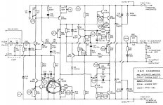
regarding c27 in arcam A60 it's used like frequency compensaton cap, many engineers think it's a bad method, but I have used this system in a preamp that actually I have designed and made.
I think that is a good way to compensate an preamp or amp. Infact, several friends of mine have request to me the PCB for making my preamp.
I think that is a good way to compensate an preamp or amp. Infact, several friends of mine have request to me the PCB for making my preamp.
Hi all,
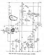
I woud propose these changes to Gulliermo's amplifier, they are showed in the photo.
1. the RC group I have added to schematic reduce the global feedback ratio to around 26 dB. This feedback network is well knowed from stasis amplifiers , but in these amp the global NFB is reduced to zero. In the Gulliermo's amplifier isn't possible reduce to zero the global NFB because it hasn't the many pairs of power bjts in the out like the stasis amplifiers have (or had).
I this moment I forgotten that a similar network is been used in some (or several.......) Nakamichi amplifiers.
I have studied very much the Gulliermo's amplifier and I think this is a very strategic but simple mod.
2. the other changes are:
tr7=tr8=mj15003 or mj15023
tr1=tr2=bc557b or bc556b
c2= 47uF 35V or 50V hight speed series bypassed with 22nF 50V cap
c3= 470uF 16V no polar electrolitic bypassed with 22nF 50V cap
3. change the c2 with a zener 16V 1/2W and in this case the r2=4,7k 1/4W and R3=10K 1/4W
- Status
- This old topic is closed. If you want to reopen this topic, contact a moderator using the "Report Post" button.
- Home
- Amplifiers
- Solid State
- Arcam A60