Definitely look at the marking of the resistors. Non of the meters I have is really accurate at reading resistances below 1 ohm. I'm sure yours is probably no better than mine! Even pulling the leads and putting the resistor right across the sockets on the meter is still inconsistent.
Help me out here...
65v vs. 64.6v... how is that an issue? I am assuming like other Aragons, this guy is dual mono? If so that reading is fine.
If not... does it have separate bridges? Swap the bridges and see if the rails react.
As for the mV vs the mA, how are you arriving at the conversion, using a calculation or summing up the voltage drops across each ER of each OP device?
"As for the mV vs the mA, how are you arriving at the conversion, using a calculation or summing up the voltage drops across each ER of each OP device?"
I believe he has popped the rail fuses out and measured the actual current draw. So I don't think there is any conversion he is using.
I believe he has popped the rail fuses out and measured the actual current draw. So I don't think there is any conversion he is using.
Back again...
Probably should have clarified the rail voltage bit... I'm sure the xformer is a 65v, had just wanted to show what I metered (64.6; equal on all rails, both channels). Will now skip the minute fractions in my measurements.... unless necessary...
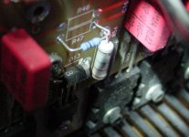
The Re resistors are actually marked as 0.32ohm (orange:red:silver:gold).
Chamberman has it right, no conversion on my current readings. Popped the rail fuses, and measured at those points.
My original measurements were at a room temperature of 22~24 celcius. Today's were done at 18 degrees Celcius...
Current draw @ 15mv bias Re:
Left channel, positive rail : 206mA
Left channel, negative rail : 160mA
Right channel, positive rail : 161mA
Right channel, negative rail : 162mA
Voltage offset at speaker outputs: Zero! (both channels)
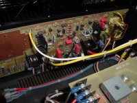
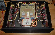
Here's a couple shots just for those curious~...
Probably should have clarified the rail voltage bit... I'm sure the xformer is a 65v, had just wanted to show what I metered (64.6; equal on all rails, both channels). Will now skip the minute fractions in my measurements.... unless necessary...
The Re resistors are actually marked as 0.32ohm (orange:red:silver:gold).
Chamberman has it right, no conversion on my current readings. Popped the rail fuses, and measured at those points.
My original measurements were at a room temperature of 22~24 celcius. Today's were done at 18 degrees Celcius...
Current draw @ 15mv bias Re:
Left channel, positive rail : 206mA
Left channel, negative rail : 160mA
Right channel, positive rail : 161mA
Right channel, negative rail : 162mA
Voltage offset at speaker outputs: Zero! (both channels)
Here's a couple shots just for those curious~...
Attachments
Would the leak be in the electrolytic(s) or could it be hiding somewhere else? If it's not a critical (gonna blow-up components) issue, I'll leave it alone for as long as my sanity can restrain my hands from wanting to fix it (esp since any work would be quite intensive; possibly over my head)...
Fantastic to hear the numbers are good and the transistors are fine.
It is the nicest sounding amp I've had in my setup. Would not think of upgrading past this point. Pondered about the 8008, but prefer to have some power left over for my other audio components (everything using the same outlet).
Fantastic to hear the numbers are good and the transistors are fine.
It is the nicest sounding amp I've had in my setup. Would not think of upgrading past this point. Pondered about the 8008, but prefer to have some power left over for my other audio components (everything using the same outlet).
Yup,
xformer--->bridges--->big electrolytics--->fuses--->jump point to channel board
There are two medium size 100uf 100v (will confirm) electrolytics on the channel boards. I had thought it might have been one of those. All look perfect. All others are wima film.
Although a ~40mA leak, minute? No worries of future self destructive potential (other than my own)?
~listening to it right now~

hahaha... groan.. hahaha... groan..
not a chance!... I'll save it for when I can afford a boat.
Happily my back is doing a lot better now.
Will be able to manage the measurements this weekend, I think. It has just been quietly sitting on my desk all week begging for attention.
measurements...
Hi!
Back in action. Got me some readings to spot leakage...
Ambient room temp 21c, measuring Re per transistor on left channel:
2sc3281
6) 14.3mv
5) 15.0mv
4) 14.5mv
2sa1302
3) 15.0mv
2) 14.5mv
1) 13.1mv (the leaker I presume??)
Back to the question... Is this worth pulling apart half the amp to replace? Though I'm guessing it could also be the contributor to that intermittent low-output breakup I had noticed. Then it would be worth the effort.
bluesmoke said:13.1mv (the leaker I presume??)
No.
Assuming exactly 0.32 ohm for all emitter resistors, you'd have about 137mA of bias through one side of the output stage and ~133 mA through the other side.
The Re's have a +/- 10% accuracy, which means that two of them can be off by 20%.
The figures actually look very good.
Not surprising, because those Toshiba numbers are known to have a close parameter spread straight from the box.
You could measure the Re value of the 13.1mV device, exchange it for a better suiting one if the bias through that one is too far off.
I'm much better with diy boat problems, ever seen an electric operated 5000lbs lifting sailboat keel ?

Weighs more than the epoxy composite hull boat itself, and saves your back.
Attachments

Input was grounded, no load on output.
Can try to test the value of that one Re, however, had been mentioned earlier that multimeters are noticeably unreliable at those values. Considering I was getting values of .5 ohms for the good ones (marked 0.32). Will go back and try anyway to see if any variation.
Just wondering where that extra 40ma could be going, considering the rest of the amp seems to be spot on. No noticeable difference in thermals.
Probably best for me to put the cover back on. Maybe waste some time building a new and improved headamp to keep my mind busy.
As for boats, I've only worked on the small plastic kind that come in a cardboard box. Very easy on the back.
Hi,
now that you have confirmed that there was no load connected, then the upper and lower Ibias MUST be balanced.
The the difference totals you have measured are down to resistor tolerance. The individual Vre are the result of resistor tolerance and Vbe variation.
It is not worth chasing this any further. They are close enough, unless you are prepared to replace the two sets of triplet Re for matched sets.
- Status
- This old topic is closed. If you want to reopen this topic, contact a moderator using the "Report Post" button.
- Home
- Amplifiers
- Solid State
- Aragon question...