Hi folks,
As suggested by Apogee I am starting this thread to explore the ins and outs of restoring my Aragon 4004 Mk 2 Amp.
I’ve just arrived on the forum with a background in electronics and electrical servicing plus a spot of design now and then. I’m also a radio amateur and restorer of vintage radios. My home stereo system consists of a pair of Thiel CS3.6 speakers, the Aragon 4004 and a Meridian 208 preamp/CD player combination (a deteriorating ergonomic nightmare that I would rather not have bought).
My original post was in the swap meet forum as I begun to look for replacement output transistors but, at the risk of some repetition, I’ll summarise my situation here.
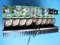
I put the Aragon Mark 2 on the workbench to check out a faulty right channel. Two power supply fuses blown, and, on DC testing the output transistors, three of them short-circuit.
Apogee has suggested the MJ11936 and MJ11946 as alternatives to the Toshiba 2SD242 and 2SB554 which I was originally contemplating using. I will likely use these transistors when I can locate some.
He also gave me these links to other posts:
1) A Mexico forum
2) Aragon question
3) Aragon 4004 MK2 output replacements
These were all very helpful. As Apogee pointed out, the Mexican post was very detailed and “Adrian” was serious enough about restoring his amp to come up with a complete list of the often-replaced passive components, electrolytic capacitors and some resistors.
I also read a great post from mightydub about upgrading the 4004 but I will need to go over it again to see if any of his improvements can be applied to the 4004 as it it without major changes to the circuitry.
I was able to obtain some information from a very helpful contact at Indy Audio Labs – the main schematics and also the parts list and positions for the Mark 2 upgrade.
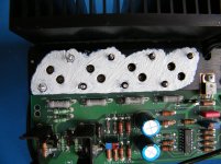
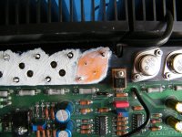
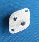
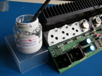
The first thing I noticed about the output transistors was that the thermal grease had dried out and was very patchy. So I will be dismounting all the transistors, cleaning off the old grease and applying some new stuff, probably the Unigrease 3000 product. When thermal grease deteriorates it's no surprise to find failing output transistors.
Secondly the two resistors on the ground board (R201 and R202) had lost their metallic paint coating due to the regular heating. They test fine at about 10 Ohms each but I will be replacing them.
Next step, I will source the MJ11936 and MJ11946.
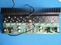
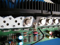
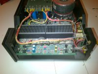
Here’s the amp during an initial inspection and before laying down a decent electrostatic protection mat:
All suggestions and input welcome.
Kind regards
donf
As suggested by Apogee I am starting this thread to explore the ins and outs of restoring my Aragon 4004 Mk 2 Amp.
I’ve just arrived on the forum with a background in electronics and electrical servicing plus a spot of design now and then. I’m also a radio amateur and restorer of vintage radios. My home stereo system consists of a pair of Thiel CS3.6 speakers, the Aragon 4004 and a Meridian 208 preamp/CD player combination (a deteriorating ergonomic nightmare that I would rather not have bought).
My original post was in the swap meet forum as I begun to look for replacement output transistors but, at the risk of some repetition, I’ll summarise my situation here.
I put the Aragon Mark 2 on the workbench to check out a faulty right channel. Two power supply fuses blown, and, on DC testing the output transistors, three of them short-circuit.
Apogee has suggested the MJ11936 and MJ11946 as alternatives to the Toshiba 2SD242 and 2SB554 which I was originally contemplating using. I will likely use these transistors when I can locate some.
He also gave me these links to other posts:
1) A Mexico forum
2) Aragon question
3) Aragon 4004 MK2 output replacements
These were all very helpful. As Apogee pointed out, the Mexican post was very detailed and “Adrian” was serious enough about restoring his amp to come up with a complete list of the often-replaced passive components, electrolytic capacitors and some resistors.
I also read a great post from mightydub about upgrading the 4004 but I will need to go over it again to see if any of his improvements can be applied to the 4004 as it it without major changes to the circuitry.
I was able to obtain some information from a very helpful contact at Indy Audio Labs – the main schematics and also the parts list and positions for the Mark 2 upgrade.
The first thing I noticed about the output transistors was that the thermal grease had dried out and was very patchy. So I will be dismounting all the transistors, cleaning off the old grease and applying some new stuff, probably the Unigrease 3000 product. When thermal grease deteriorates it's no surprise to find failing output transistors.
Secondly the two resistors on the ground board (R201 and R202) had lost their metallic paint coating due to the regular heating. They test fine at about 10 Ohms each but I will be replacing them.
Next step, I will source the MJ11936 and MJ11946.
Here’s the amp during an initial inspection and before laying down a decent electrostatic protection mat:

All suggestions and input welcome.
Kind regards
donf
Hi Donf
Looks like you are real dedicated to mkae this amp last forever.
If that is your plan I would suggest you upgrade it even further, to include a Zobel filter and an output coil.
Link to Rod Elliot article
The reason for that is, that back at the time when Aragon designed the 4004 there was only neglible radio noise in the air, but today you have mobile phones signals, wi-fi routers, cheap switchmode PSUs for all your electronics, halogene lamps, etc etc.
All that noise is picked up by the speaker cables and radiates directly into the amplifiers feedback loop, and makes it noisy and humming.
This is something I experienced myself when I had the Aragon 4004 amp in my system ... a small amount of constant white noise, and some serious humming when I turned on my three 60W halogene spotlights.
Adding a circuit exactly as in the above link cured all of that.
I know it is not part of the original schematic, and some people in this forum advices against output coils - but for this amp it works and it was necessary for me to add it.
If you experience no noise problems you can maybe do without it, but just be aware that this amp can pick up these noises.
Good luck with your restoration.
Aragon 4002 Mk 2 amp restoration
Hi Nrik,
Many thanks for your post. Yes! I am aware of rf pick-up. More than once I've heard local stations demodulated through an amp let alone instability due to noise. As an electrician, I’m also familiar with the rf mess that low voltage halogen lamp power supplies throw out and that’s why I never recommend them. I go for mains powered lamps.
It looks like mightydub’s amp schematic sports the same network on its output.
I have never had problems with this sort of pick-up but there’s always a chance so I will think seriously about adding the network. It will need a decent current rating so if you have a source for suitable components that would be useful.
I checked out Rod Elliot’s article, thank you. On the other hand I don’t have the test gear needed (other than a 100Mhz scope) to determine exactly how the network will behave dynamically on the amplified signals. Given that it’s on the output I’d expect its influence to be small. Without going into design detail, I can think of a couple of questions.
1) If one of the functions of the network is to reduce the sensitivity of the amp to high frequency oscillation why not introduce a pole earlier in the amplifier itself by way of a suitable simple network?
2) If the network is a real help in preventing local oscillation (in the power output stage) what is its likely interaction with any filter networks in the speakers themselves? (Particularly at low frequencies, even if they are connected to what is effectively a transmission line, the speaker cable). My Thiels have a 25-element network in their enclosures.
3) Do other high quality amps use this network?
Admittedly I need to get back up to speed with my circuit analysis and read up on the Zobel network application to audio amps. I can do no better than Rod Elliot’s references in his article.
donf
1) If one of the functions of the network is to reduce the sensitivity of the amp to high frequency oscillation why not introduce a pole earlier in the amplifier itself by way of a suitable simple network?
Because it is not meant to reduce instabilities in the amplifier itself ( there will be other measures for that already) but to isolate incoming RF from outside the amp. If you analyse the circuit from the output and inwards, you will see that the coil and the capacitor forms a 2nd order filter for whatever is coming in that way, and from the amp towards the speakers the capacitor+ resistor should not affect the sound because of the extremely low output impedance of the output, and only the low-value coil will be in series with the speaker cables.
2) If the network is a real help in preventing local oscillation (in the power output stage) what is its likely interaction with any filter networks in the speakers themselves? (Particularly at low frequencies, even if they are connected to what is effectively a transmission line, the speaker cable). My Thiels have a 25-element network in their enclosures.
Of course there will be an impact, but because of the very low values the effect in the audible range would be very small, and it would definitely be preferred over an oscillating amp.
See this thread for knowledge of how bad it can be.
As you mention yourself it is advised too use really low-loss quality components, such as a big thick-wired aircore inductor.
Oh yes - quite a few. Do as much research as you find necessary, but I am sure you will see that it is quite normal even in "high quality" amplifiers.3) Do other high quality amps use this network?
I have used, repaired and built many amps, and usually incoming RF is not a big problem, but I found the Aragon 4004 to be extremely sensitive to this matter. I can not explain or analyse why it was so, but as I said the very audible noise went away when adding the zobel filter and the output coil.
For the reference see also what other DIY-forum-members thinks in this lengthy discussion on output coils.
Last edited:
Aragon 4004 Mk 2 restoration
Nrik,
Good points, thank you.
On the first point, yes, I think I was staring into the wrong end of the filter - up too late! I think I'll draw that circuit out again and find a utility that will draw up transfer functions, possibly something like this site where I can satisfy myself of the filter's function and play around a bit. This is good stuff - it's forcing me to return to some of the basics that I've forgotten over the years.
On the second point, as the thread you identified seems to show, there is a difference with the coil. But essentially it will be easier to just try it and see.
On the third point, I acknowledge your experience here. Given what you have found with the Aragon it seems wise to try the filter. I can probably do some tests with a signal generator and an oscilloscope with some generated interference.
donf
ON components - update
Apparently the ON Semiconductor components suggested by Apogee (MJ11936 and MJ11946) for the Aragon 4004 output replacements are not available.
They have suggested the MJ15003G and MJ15004G
The schematic I have for the Aragon (dated 12th May 1987) has those transistors as the outputs anyway.
donf
Apparently the ON Semiconductor components suggested by Apogee (MJ11936 and MJ11946) for the Aragon 4004 output replacements are not available.
They have suggested the MJ15003G and MJ15004G
The schematic I have for the Aragon (dated 12th May 1987) has those transistors as the outputs anyway.
donf
Upgrade Aragon 4004 MK ll power supply capacitors.
Modifying Aragon 4004 MKII power supply capacitors - Page 2 - AudioKarma.org Home Audio Stereo Discussion Forums
Member Chamberman has worked on Aragon and Acurus amps for years. Contact him regarding the ingot Mk ll power supply board.
Modifying Aragon 4004 MKII power supply capacitors - Page 2 - AudioKarma.org Home Audio Stereo Discussion Forums
Member Chamberman has worked on Aragon and Acurus amps for years. Contact him regarding the ingot Mk ll power supply board.
Hi Don,
Glad you set up this thead!
This was my response:
Yes they are available and they are better than the 15003 & 15004 units. They are basically improved upon copies of the original perforated emitter units from Toshiba.
Also, regarding thermal grease, I'm not familiar with the stuff you mentioned but it's intriguing. As luck would have it, I ordered stuff today. To see what I ordered, search DOW CORNING 340 DC340 on eBay as it too is good thermal grease.
I'll be following this with interest. I'd also love copies of the info you received from the Mondial tech if you'd be willing to share it.
Hope this helps,
Steve
Glad you set up this thead!
This was my response:
The short answer is use MJ21193G & MJ21194G as replacement output transistors. You will find as long as they're from the same lots that their device to device tolerance is much closer and matching should be close enough to not be required.
Yes they are available and they are better than the 15003 & 15004 units. They are basically improved upon copies of the original perforated emitter units from Toshiba.
Also, regarding thermal grease, I'm not familiar with the stuff you mentioned but it's intriguing. As luck would have it, I ordered stuff today. To see what I ordered, search DOW CORNING 340 DC340 on eBay as it too is good thermal grease.
I'll be following this with interest. I'd also love copies of the info you received from the Mondial tech if you'd be willing to share it.
Hope this helps,
Steve
Last edited:
Hi Folks,
Bit late on this one. Been away for a while and just catching up.
The dismantled Aragon is sitting on a trestle table which has developed a worrying bow in it .. so I transferred it to a slightly better table.
First, thanks llwhat for confirming the correct transistors and also Apogee (nice to see you here!) for the same. I must have transposed those numbers from some other project - amazing what slips in even after double-checking my replies.
I haven't checked here in the UK but if you can recommend a US source that would give me a decent back-up.
Apogee, on the subject of grease, the Dow Corning stuff looks good although I haven't had time to compare its thermal conduction characteristics with the stuff I have. Thermal conductivity of the UniGrease 3000 is 3.0W/mK and it looks very soft so it will flow well into very small imperfections on the metal surfaces. Operating temp: -50 to +200°C.
The manufacturer of the grease, Universal Science, was very good indeed in dealing with my enquiries and they sent me a small complimentary half bottle of the grease which will likely do the output sets of both channels.
And thank you Audiostar for the lead on the power supply capacitors. I'll check it out.
Right, so, for schematic info here are the three files kindly sent to me by a contact at Indy Audio.
View attachment 4004 output module.pdf
View attachment 4004 power supply.pdf
View attachment 4004 board layout.pdf
Just a note on modifications and improvements, although they appear to be worthwhile, one thing to keep in mind here is that strictly speaking this project is more of a restoration than a change or improvement scenario. However, I know there's often a fine line here and I still welcome comments on improvement.
donf
Hi Folks,
Bit late on this one. Been away for a while and just catching up.
The dismantled Aragon is sitting on a trestle table which has developed a worrying bow in it .. so I transferred it to a slightly better table.
First, thanks llwhat for confirming the correct transistors and also Apogee (nice to see you here!) for the same. I must have transposed those numbers from some other project - amazing what slips in even after double-checking my replies.
I haven't checked here in the UK but if you can recommend a US source that would give me a decent back-up.
Apogee, on the subject of grease, the Dow Corning stuff looks good although I haven't had time to compare its thermal conduction characteristics with the stuff I have. Thermal conductivity of the UniGrease 3000 is 3.0W/mK and it looks very soft so it will flow well into very small imperfections on the metal surfaces. Operating temp: -50 to +200°C.
The manufacturer of the grease, Universal Science, was very good indeed in dealing with my enquiries and they sent me a small complimentary half bottle of the grease which will likely do the output sets of both channels.
And thank you Audiostar for the lead on the power supply capacitors. I'll check it out.
Right, so, for schematic info here are the three files kindly sent to me by a contact at Indy Audio.
View attachment 420602
View attachment 420603
View attachment 420604
Just a note on modifications and improvements, although they appear to be worthwhile, one thing to keep in mind here is that strictly speaking this project is more of a restoration than a change or improvement scenario. However, I know there's often a fine line here and I still welcome comments on improvement.
donf
Hi Donf,
I couldnt help but noticed a major error on the PSU schematic you posted: either the diode bridges or the PSU caps and terminals are reversed!!!
Also, I'm servicing a 4004 with an issue lies somewhere between the PSU of channel B and the Speaker protection circuit that make its relay wont close. I found that the supply for this circuit on my amp is somewhat different to yours.
I will update soon as I found the cause of the issue on my amp.
Regards,
Duong
Hey Duong!
Just got your message. Well, you're quite right! The diode bridges are inverted and since all the schematics I obtained were supposedly from Aragon design we must assume that this was a drawing oversight. A quick check of the rectifier and capacitor PCB showed that the right voltages were going to the right places. For example, there is +70V at F301 and -70V at F303. The diode bridge D301 negative terminal is connected to the negative terminal of C301. Similar story for the other rectifiers and capacitors. So we'll just have to flip those diode bridges the right way around!
All the best
donf
Replacing the transistors on an Aragon 4004 output module
Duong's message finally galvanised me into action about the restoration of the Aragon 4004. I have, in fact, managed to get one channel assembly done and what follows is the procedure I used.
I have tried to upload the photos to this site but I continually get errors. The document I did is very large so no doubt I'm running into file size problems.
Therefore, I'll have to get this up in several postings. I am no editing guru so suggestions as to how to get readers the entire file are welcome.
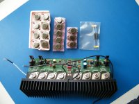
Before starting, here's what I had on the bench, the right channel module and the new parts. Transistors as discussed earlier in this thread supplied by DigiKey (excellent service) and thermal grease supplied by Unigrease (excellent support as well). Also present are the replacements for resistors R201 and R202.
Aragon 4004 - replacing transistors on an output module
1) Clean and prepare the heat sink and thermal washers. I used an old clean handkerchief and a cleaning cloth designed to remove dirt from surfaces (not abrasive)
Renovation of an Aragon 4004 MkII amplifier – July 2014
Procedure used to replace the main output transistors on the right and left channel amplifier modules using Unigrease 3000 thermal grease.
1) Clean and prepare the heat sink and thermal washers. I used an old clean handkerchief and a cleaning cloth designed to remove dirt from surfaces (not abrasive)
Fig 1: Heat sink cleaned.
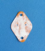
Fig 2: Thermal washers very carefully cleaned of the old grease without buckling them.
Aragon 4004 - replacing transistors on an output modula
2) Apply grease to the heat sink. The ideal is to fill the air gaps on the anodised aluminium heat sink with an even layer of grease. In practise the grease, while very flexible, can “bunch up” into spots so I applied a layer with a small paintbrush evening it out and avoiding thick patches. Excess grease would make it difficult to compress and could even cause air gaps that would decrease thermal conductivity.
3) Apply a thin layer of grease to one side of a thermal washer
Aragon 4004 - replacing transistors on an output module
4) Apply the washer to the heat sink. This may vary from normal practice where you stick the thermal washer to the transistor first but here I wanted to use the heat sink as a support to press down on the thermal washer and carefully work it onto the heat sink thus optimising the spread of the thermal grease.
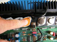
Fig 5: Applying the thermal washer to the heat sink. Press gently with a finger onto the thermal washer and carefully work it down to spread the grease as evenly as possible between the washer and the heat sink.
5) Put a thin layer of grease over the top of the thermal washer mounted on the heat sink. Don’t overdo it – just go for an even spread of the grease. I applied this with the paintbrush and wiped it very slightly with my finger to smooth off any excess.
4) Apply the washer to the heat sink. This may vary from normal practice where you stick the thermal washer to the transistor first but here I wanted to use the heat sink as a support to press down on the thermal washer and carefully work it onto the heat sink thus optimising the spread of the thermal grease.

Fig 5: Applying the thermal washer to the heat sink. Press gently with a finger onto the thermal washer and carefully work it down to spread the grease as evenly as possible between the washer and the heat sink.
5) Put a thin layer of grease over the top of the thermal washer mounted on the heat sink. Don’t overdo it – just go for an even spread of the grease. I applied this with the paintbrush and wiped it very slightly with my finger to smooth off any excess.
Aragon 4004 - replacing transistors on an output module
6) Apply a layer of grease to the transistor to be mounted. Again, I applied this with the paintbrush and spread the grease as evenly as possible. Be careful NOT to get grease on the base and emitter leads as you will note in Fig 7 there’s a bit on one of the leads which had to come off!
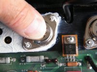
7) Fix the transistor in position on the heat sink. Apply firm pressure on the transistor for about 10 seconds and then screw the transistor to the heat sink. In the case of the Aragon 4004 assembly the transistor securing nuts are equipped with grip washers. Screw the bolts down sufficient for the grip washers to take and then NO MORE or you risk buckling the transistor case or even stripping the thread of the mounting bolt. Strictly speaking the torque spec for the nuts is 8 inch pounds (0.9nm) so the best solution is to use a proper torque screwdriver. See Figs 8, 9 & 10.
- Status
- This old topic is closed. If you want to reopen this topic, contact a moderator using the "Report Post" button.
- Home
- Amplifiers
- Solid State
- Aragon 4004 Mk2 restoration
