Sure, old thread....Ever figure out your tracking rail adustments? One scope lead on + rail, another on the - rail, third lead on output. I used a 4-ohm power resistor for the load. (Need to float scope! The only probe ground lead that was connected was the output probe across the resistive load.)
With the input voltage set to 0V, you should have 3 parallel signals displayed after adustments are completed: +6v, 0v, -6v. Adust pots slowly to get these readings - I set to approx +6.5V / -6.5v.
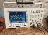
This is what the adjusted supplies look like with a 40hz sinewave on the input. (I don't recall input voltage setting for the scope view - think it was approx 50mv or so). I also check with the subs volume pot set to 0db, and maximum input (think it was 150mV) that the tracking supplies are always approx 6v above/below the input sinewave, so the output does not show any signs of clipping at their peaks. You can also do this with a DVM as well with 0V on the input, but you will not be able to check the settings accurately with an input signal applied. Not sure if this helped? Or too late............
With the input voltage set to 0V, you should have 3 parallel signals displayed after adustments are completed: +6v, 0v, -6v. Adust pots slowly to get these readings - I set to approx +6.5V / -6.5v.
This is what the adjusted supplies look like with a 40hz sinewave on the input. (I don't recall input voltage setting for the scope view - think it was approx 50mv or so). I also check with the subs volume pot set to 0db, and maximum input (think it was 150mV) that the tracking supplies are always approx 6v above/below the input sinewave, so the output does not show any signs of clipping at their peaks. You can also do this with a DVM as well with 0V on the input, but you will not be able to check the settings accurately with an input signal applied. Not sure if this helped? Or too late............
Attachments
- Status
- This old topic is closed. If you want to reopen this topic, contact a moderator using the "Report Post" button.