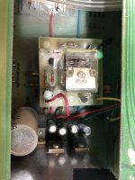
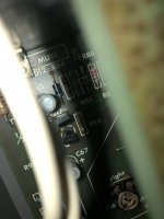
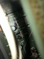
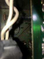
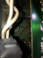
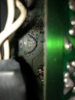
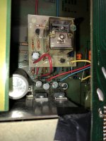
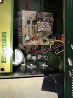
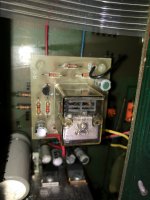
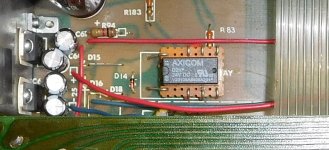
I have two APT preamps. Both working. The main issue...the pictures attached called "APT Holman factory mod" are my original unit I purchased in 1980. The relay was sticking on the left channel so I decided to open up the bottom cover. Please take a close look at these pictures labeled "APT Holman factory mod". The factory did the mod in 1986 or so and cut the mute relay components out and did this monstrosity. I have three brand new relays I acquired in the last 3 months. I was able to inject some Deoxit into the jump board relay and it seems to have improved. The real fix is to return this unit to its original condition and install the relay back to the PC board. I have two problems. There are three transistors. The schematic is so small and illegible that I cannot tell if they are Q17, q18 and Q19 are PNP or NPN transistors. Second problem, both 2n5087 and 2sc1345e are no longer in production. Now it looks like APT took those transistor and mounted them to the relay board in the picture. But one is a 2n3906?? I cannot read the others. I have the other preamp and those pictures are labeled "APT Holman Standard Relay" and it shows how it should be built or repaired in my view. I want to return my original unit to factory board parts and really need DIYer's advice on the best way to approach the repair. I know many of you have helped me before and I have beginner to lower intermediate skills. I have a temperature controlled soldering iron and a solder sucker. I recently recapped a Hafler DH110 so I am able to recap units if that helps. I work very slow and the unit that needs repaired have a partial wire sticking out of the board. Thanks for any advice.
Attachments
-
 APT Holman Preamp Factory modified relay installed under the mod 1 factory repair1.JPG338 KB · Views: 264
 -
 APT Holman Preamp with standard relay3.JPG366.7 KB · Views: 251
 -
 APT Holman Preamp with standard relay2.JPG247 KB · Views: 232
 -
 APT Holman Preamp with standard relay1.JPG246.8 KB · Views: 211
 -
 APT Holman Preamp Factory modified relay installed under the mod 1 factory repair7.JPG267.9 KB · Views: 216
 -
 APT Holman Preamp Factory modified relay installed under the mod 1 factory repair6.JPG274.9 KB · Views: 212
 -
 APT Holman Preamp Factory modified relay installed under the mod 1 factory repair5.JPG298.9 KB · Views: 232
 -
 APT Holman Preamp Factory modified relay installed under the mod 1 factory repair4.JPG376.3 KB · Views: 243
 -
 APT Holman Preamp Factory modified relay installed under the mod 1 factory repair3.JPG359.7 KB · Views: 242
 -
 APT Holman Preamp Factory modified relay installed under the mod 1 factory repair2.JPG365 KB · Views: 253
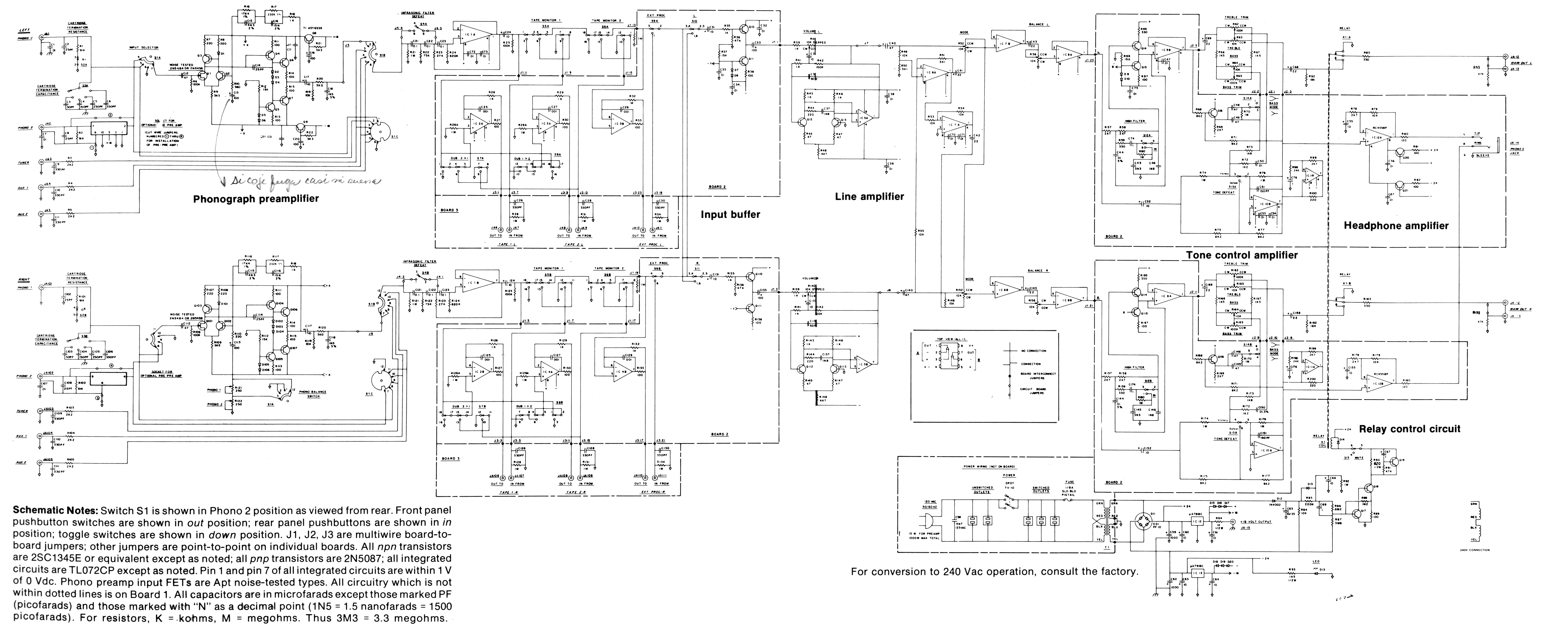
I searched and found several websites with the manuals. This one http://www.amplimos.it/images/apt-holman-preamplifier-service-manual.pdf had a schematic that was fairly readable. The manual also describes the mute circuit near the beginning.
Did you ever figure out the relay issue? I have an Apt Holman that I just finished restoring. While I was waiting for replacement ribbon cables I tested the muting relay with only the main board connected. It worked as expected (4-5 seconds until it clicks). Today I received the ribbon cables and put the switch assembly board in, and the relay stops working. I've narrowed it down to the 11 pin ribbon being connected/disconnected determining whether or not the relay will work. So either there's a fault on the switch assembly board, or it's affecting the relay circuit in another way.
I too have thought about reverting it to the original circuit, but then the problem is the revised relay won't fit the main board... Also, I'd have to order a bunch of parts to bring it back to original, and it still might not work.
I guess tomorrow I'm going to try to reverse engineer the revised version and come up with a schematic...
Please draw the circuit. It is a an output muting circuit so one can make it much smaller with a micro relay as there is no power to switch. If it is an original mod it is a peculiar one. I would make it a muting to GND muting to keep relay contacts out of the signal path. Shorting the output to GND so to speak, it has a capacitor and a resistor so all is possible without drawbacks.The way it is made according to the manual is that the relay switches outputs to RCA after a while. That means that a bad relay will cause crackling.
Don't worry too much about original etc. as manufacturers have Mondays too so there exist original design errors/imperfections, original mistakes, original mediocre choices etc.
Don't worry too much about original etc. as manufacturers have Mondays too so there exist original design errors/imperfections, original mistakes, original mediocre choices etc.
Last edited:
@jean-paul: Thanks for the reply!
I will take the board out and draw up a schematic tomorrow.
Note that this was an actual factory modification, and it looks just like @Marksd's. This preamp came with extensive documentation including correspondence between the original owner and Apt Corporation requesting the revision in 1982. While the Apt Holman is extremely well documented, they apparently didn't document the factory muting relay revision. Here's the letter and the repair invoice for anyone that's interested:

This muting relay daughter card has three flying leads from the main board (+18. +16 and GND), and also there are 8 jumpers connecting the relay pins back down to the main board. I'm not sure why all the relay pins were jumpered back to the main board if the relay circuit is contained to the daughter board. Here's another view showing the 8 jumpers between the boards:

This view shows the original circuit was all pruned out, and holes were drilled in the PCB to get +18V, +16V and ground up to the board via the red, yellow and black jumpers:

I mentioned it before but I'm concerned there's a problem on the switch assembly board because the muting relay works when J2 is disconnected... Aside from sketching the circuit, I'm also planning to record the relay coil voltages, and the +16/+18/GND jumper voltages with and without the J2 ribbon connected to see what's changing.
I'll be back with more information tomorrow.
Cheers
I will take the board out and draw up a schematic tomorrow.
Note that this was an actual factory modification, and it looks just like @Marksd's. This preamp came with extensive documentation including correspondence between the original owner and Apt Corporation requesting the revision in 1982. While the Apt Holman is extremely well documented, they apparently didn't document the factory muting relay revision. Here's the letter and the repair invoice for anyone that's interested:
This muting relay daughter card has three flying leads from the main board (+18. +16 and GND), and also there are 8 jumpers connecting the relay pins back down to the main board. I'm not sure why all the relay pins were jumpered back to the main board if the relay circuit is contained to the daughter board. Here's another view showing the 8 jumpers between the boards:
This view shows the original circuit was all pruned out, and holes were drilled in the PCB to get +18V, +16V and ground up to the board via the red, yellow and black jumpers:
I mentioned it before but I'm concerned there's a problem on the switch assembly board because the muting relay works when J2 is disconnected... Aside from sketching the circuit, I'm also planning to record the relay coil voltages, and the +16/+18/GND jumper voltages with and without the J2 ribbon connected to see what's changing.
I'll be back with more information tomorrow.
Cheers
I removed the 'upgraded' mute circuit today and started to put together a schematic on circuitlab.com, but then I got locked out after an hour and told to pay an annual membership to continue using. Too bad, because it seemed like a good tool but not something I'd use a lot.
I ended up desoldering the relay from the upgrade board and using flying leads to connect it directly to the old location on the main board. This bypasses the timer circuit, but the mute button still works. The downside is that if you turn off the preamp before the amp, you get a loud THUMP through the speakers. I remember old Naim olive preamps doing this because they didn't have output relays, and the user had to remember to turn off the amp first. So this isn't ideal.
When I recapped the Apt I replaced all the electrolytics, including the two on the upgraded mute PCB, so those aren't likely to be the issue. There are three transistors on the board, and I suppose one of them could be failing. The diodes and resistors are probably ok.
I seem to have four options at the moment:
1) Leave it like it is and just turn off the amp before the preamp. This isn't ideal.
2) Try to figure out the issue with the upgraded circuit, which is undocumented, and may have had incorrect components when I bought the preamp. The upgrade board is still intact except for the relay I removed.
3) Order parts to recreate the original circuit, and try to find a relay that will fit the original PCB location (or use flying leads). This seems like an ok option but I'm hesitant because it might not work either. Why was there an upgraded circuit in the first place?
4) Try to figure out a new implementation with a timer IC and a smaller signal relay. This sounds like a good idea, but I'm out of my element. If the existing relay won't open before the THUMP occurs, I'm not sure how the new circuit would open any faster and prevent it.
@wiseoldtech: It was butchered by the factory -- this was supposedly an 'upgrade'. See the photo of the correspondence between the owner and APT in my earlier post.
I am putting together an order to put back the original parts in the original circuit. Fingers crossed.
I am putting together an order to put back the original parts in the original circuit. Fingers crossed.
The muting is obviously needed and therefor a good thing and not useless luxury. Bringing it back to original condition is not the solution as the extra PCB was added for a reason. The way it was done with a way too heavy relay totally not suitable for muting purposes was plain bad and esthetically not appealing. It is clearly a badly executed mod. The way it first was done as seen in the schematic with contacts in series with the outputs also is not OK. Solution: make it better (hint: which is not by omitting muting). You can easily draw such a simple circuit with a mini relay (a sealed telecom relay with gold contacts), a handful of other components and use the same footprint as the old "original mod" circuit. Challenge!
Relays need a certain current to switch to function normally. For non power switching one uses small relays that have less chance on contact corrosion and don't need higher current switching. Adding a new muting circuit using only one of either supply voltages is easiest. A member here used to sell mini PCBs with a tiny relay on it for exactly this purpose. The "shorting outputs to GND" and after a while opening the contacts works perfectly and definitely better than the original upgrade circuit. More than enough information to make it better than it was. Just think: purpose and how to do it best and don't focus on original as that original mod was terrible. One likely wants a 5 second delay at power on and immediate shorting of outputs at power down. The circuit will not interfere or have any influence on signal quality this way. Worst case fault (but one will likely never experience that) is then failing relay/contacts and then no muting.
BTW that were indeed very old electrolytic caps. Please clean the PCB. Replacing those TL072s for good opamps will be a true upgrade.
* a handdrawn circuit for further evaluation is not a bad thing to have. No software needed.
Last edited:
@jean-paul:
I understand what you're recommending, and I can more or less picture the circuit you're describing. But I don't have the experience to design it. For instance, to ensure that the output is shorted before the thump.
Note that the updated muting circuit modification is almost completely reversible. The only irreversible modifications are 6 holes holes in the PCB. 3 for the standoffs, and 3 for the +18V, +16V and GND jumpers.
The photos I posted above are from before I started replacing parts. At this point all electrolytics have been replaced with Nichicon ES and PW, and all opamps have been replaced with OPA2314s, TLE2072 for volume, and a new RC4558P for the headphone amp. The work was mostly completed a few months ago, but I've been waiting on the ribbon cables for 2+ months.
Here's more or less what it looks like after the overhaul. Yes, the PCB is cleaner on both sides now.
Last edited:
As a tech I only think: that is a lot of possible wearout/failure modes, unneeded features and possibly bad switches (therefor I never use preamps but ultra simple setups) ") Anyway you could focus on the muting circuit and try to find a circuit plain and simple that runs on the voltage as available in the device. I think I have put enough time in your issue with detailed description to improve it.
Anyway you could focus on the muting circuit and try to find a circuit plain and simple that runs on the voltage as available in the device. I think I have put enough time in your issue with detailed description to improve it.
Anyway you could focus on the muting circuit and try to find a circuit plain and simple that runs on the voltage as available in the device. I think I have put enough time in your issue with detailed description to improve it.
Last edited:
@Marksd:
I have 3 APT Holman preamps and have rebuilt/repaired each of them. The mute circuit is a common weak point in this preamp, but almost always related to the relay itself. I've never seen this factory "upgrade", but its rarity suggests the original circuit works well (and it's not a complicated or unusual delay/mute relay circuit either), except the relays APT used were not great.
Jean-Paul gave you the solution - a small-signal relay, sealed, gold contacts, high quality. That is a common solution to this problem. If you have a transistor tester you can verify the operation and type (NPN vs. PNP) of the transistors on the addon board, or you can revert this back to original configuration and either make an adapter board for the new, smaller relay, or dead-bug the new relay, which is what the guy who does most APT repairs does. The schematic in the manual is easier to read than the one taped to the bottom of the chassis. There are new replacements for the transistors, as well.
You've decided not to keep this, so like Jean-Paul, I won't go into the other refinements that can be made or the selection of op amps, since you've already made your selections. However, you could get the mute circuit working properly, and as long as the preamp is working properly, I think you'd find it is of very fine performance, even if you don't prefer the extensive features.
Here's how I repaired one preamp:
Attachments
I had the same problem, but no factory patch jobs. I just removed the original relay and replaced it with an Omron (6k maybe?). and the usual diode to prevent back current. ignore the junk internet suggestions about trying to fix the original relay contacts with paper or some such .
from what I remember, you need to be a little careful on what wires go where - I don't remember the specifics but there was a simple difference between the 2 relays. I chose the replacement relay by seeing what other preamps use for relay based volume controls. if it's good enough for volume control, it's good enough for a mute circuit.
if you'd like, I can open it up and take a picture for you.
@Marksd:
I have 3 APT Holman preamps and have rebuilt/repaired each of them. The mute circuit is a common weak point in this preamp, but almost always related to the relay itself. I've never seen this factory "upgrade", but its rarity suggests the original circuit works well (and it's not a complicated or unusual delay/mute relay circuit either), except the relays APT used were not great.
Jean-Paul gave you the solution - a small-signal relay, sealed, gold contacts, high quality. That is a common solution to this problem. If you have a transistor tester you can verify the operation and type (NPN vs. PNP) of the transistors on the addon board, or you can revert this back to original configuration and either make an adapter board for the new, smaller relay, or dead-bug the new relay, which is what the guy who does most APT repairs does. The schematic in the manual is easier to read than the one taped to the bottom of the chassis. There are new replacements for the transistors, as well.
You've decided not to keep this, so like Jean-Paul, I won't go into the other refinements that can be made or the selection of op amps, since you've already made your selections. However, you could get the mute circuit working properly, and as long as the preamp is working properly, I think you'd find it is of very fine performance, even if you don't prefer the extensive features.
Here's how I repaired one preamp:
Thanks for the reply. I am planning to revert to the original mute circuit to see if it operates correctly, and if so I will probably do the dead bug style mod to get a signal relay working. I'll probably preserve the existing design (signal going through relay) just to keep it simple for now.
Before I disassembled the 'factory upgrade' circuit I did some measurements of coil voltages to see if I could find out why it wasn't operating with the J2 jumper ribbon connected. With J2 disconnected, the coil voltage was 27.7V unmuted and 17.2 muted. With J2 connected, the coil voltage was 23.3V unmuted and 14.6V muted. I believe this had to do with the slight voltage drop (200mV) on the +16V rail when J2 is connected and is powering devices on the switch assembly board. But even so, the circuit wasn't performing well if it was only able to change the coil voltage slightly between mute/unmute states. I would have expected something closer to the ideal +24V/0V for the unmuted/muted coil voltages.
Anyway, I'm going to order the parts today to repopulate the original muting circuit, as well as a small signal relay.
Thanks. If the relay was actually functioning but had dirty contacts that would have been one story. But it wasn't engaging at all in my case, so it seems to be a problem with the circuit instead. I have some perf board on the way so it will be pretty easy to adapt to other relay pinouts.I had the same problem, but no factory patch jobs. I just removed the original relay and replaced it with an Omron (6k maybe?). and the usual diode to prevent back current. ignore the junk internet suggestions about trying to fix the original relay contacts with paper or some such .
from what I remember, you need to be a little careful on what wires go where - I don't remember the specifics but there was a simple difference between the 2 relays. I chose the replacement relay by seeing what other preamps use for relay based volume controls. if it's good enough for volume control, it's good enough for a mute circuit.
if you'd like, I can open it up and take a picture for you.
I had the engaging problem too. if you "pump" the relay switch, to just before the switch makes contact to where it doesn't, do it rapidly, it would sometimes work. A new relay fixed both the engagement problem and the one channel being out. all for a few dollars and a lot of headaches to figure it out.
Here's how I did it, I thought it wasn't as sloppy as this. please forgive me, honestly, my skills have improved over the years!
also, I did some other mods that you may see - they're unrelated to the relay/mute AFAIK.
I also have an excellent quality document of the entire circuit. much better than what's commonly available online or on the back of the unit. let me know if you need it.


also, I did some other mods that you may see - they're unrelated to the relay/mute AFAIK.
I also have an excellent quality document of the entire circuit. much better than what's commonly available online or on the back of the unit. let me know if you need it.
- Home
- Source & Line
- Analog Line Level
- APT Holman Preamps and relay repair