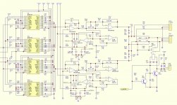
That kind of configuration looks rather like a GIC (generalized impedance converter). I haven't plugged in the specific Zs to work out what kind of impedance is being created there, but if you take a look at the schematic here you may notice similarities - https://electronics.stackexchange.com/questions/130632/general-impedance-converter
The last page (p10) of the PCM63 datasheet has a similar opamp configuration for the output filtering.
The last page (p10) of the PCM63 datasheet has a similar opamp configuration for the output filtering.
Last edited:
At first looked much like a frequency dependent negative resistor to me... but I'm not sure because it has a capacitor where that circuit branch connects to ground (Z5 in the image below) whereas a FDNR has a resistor there. Anyway, it is some kind of generalized impedance converter of this form:
Oops I see Abraxalito beat me to this conclusion.
Edit: On second thought maybe I was right. Here is an example of FDNRs used for filtering:
https://www.silvaco.com/examples/gateway/section1/example7/index.html
https://www.silvaco.com/examples/gateway/section1/example7/GIC.png
Also, see:
http://www.diyaudio.com/forums/part...rs-frequency-dependent-negative-resistor.html
Last edited:
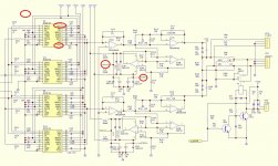
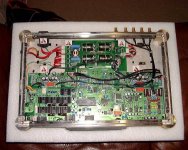
No, I only see +15,-15V being fed to the NE5532s. Via inductors.
Attachments
At first looked much like a frequency dependent negative resistor to me... but I'm not sure because it has a capacitor where that circuit branch connects to ground (Z5 in the image below) whereas a FDNR has a resistor there. Anyway, it is some kind of generalized impedance converter of this form:
Oops I see Abraxalito beat me to this conclusion.
Edit: On second thought maybe I was right. Here is an example of FDNRs used for filtering:
https://www.silvaco.com/examples/gateway/section1/example7/index.html
https://www.silvaco.com/examples/gateway/section1/example7/GIC.png
Also, see:
http://www.diyaudio.com/forums/part...rs-frequency-dependent-negative-resistor.html
I see the output connected to the +input of the second 5523, but where's the input?
Cheers George
The schematic looks like it was created in Protel. In Protel pin names within the outline of ICs are not the same as net names (attached to wires). So those VCCs you've circled aren't the same.
The input's going to pin5, U19B on the top one, U18B on the bottom.
The input's going to pin5, U19B on the top one, U18B on the bottom.
Last edited:
The schematic looks like it was created in Protel. In Protel pin names within the outline of ICs are not the same as net names (attached to wires). So those VCCs you've circled aren't the same.
The input's going to pin5, U19B on the top one, U18B on the bottom.
So would they be test V points, or maybe inputs from somewhere, that I asked above?
Can that they wouldn't be inputs as they are at v rail potential.
Cheers George
I see the output connected to the +input of the second 5523, but where's the input?
Cheers George
It's a grounded FDNR. If you look at the figure I posted, the connection to the rest of the circuit is done at left, next to Z1, and is grounded at right. Just think of it like a component created by a subcircuit that has properties (resistance and reactance) that are not possibly in a real world component.
One connection to the FDNR in the schematic that you posted is, for example, done between R148, R144, and R126. That FDNR consists of U19A, U19B, C150, R137, R139, R142, and C154 and connects to "AG" (analog ground).
Last edited:
It's a grounded FDNR. If you look at the figure I posted, the connection to the rest of the circuit is done at left, next to Z1, and is grounded at right. Just think of it like a component created by a subcircuit that has properties (resistance and reactance) that are not possibly in a real world component.
One connection to the FDNR in the schematic that you posted is, for example, done between R148, R144, and R126. That FDNR consists of U19A, U19B, C150, R137, R139, R142, and C154 and connects to "AG" (analog ground).
So what do you think it does in laymans terms Charlie?
Cheers George
This is what I found a grounded FDR does, a bloody sharp LP filter. If indeed that's what it is.
https://www.researchgate.net/public...-impedance-and-phase-of-circuit-in-Fig-3a.png
Also just found this, if it's the same thing. Must admit this player does sound very good.
http://www.diyaudio.com/forums/digi...-using-fdnrs-nos-dac-anti-imaging-filter.html
Cheers George
https://www.researchgate.net/public...-impedance-and-phase-of-circuit-in-Fig-3a.png
Also just found this, if it's the same thing. Must admit this player does sound very good.
http://www.diyaudio.com/forums/digi...-using-fdnrs-nos-dac-anti-imaging-filter.html
Cheers George
Last edited:
Looks like a high Q (say about 10) low pass filter. You can get that with a 2nd order Sallen-Key provided your active element has enough GBW. No intrinsic need for FDNR.
The FDNR in your original schematic looks to be integrated into a MFB low pass in a config I've not come across before.
The FDNR in your original schematic looks to be integrated into a MFB low pass in a config I've not come across before.
Looks like a high Q (say about 10) low pass filter. You can get that with a 2nd order Sallen-Key provided your active element has enough GBW. No intrinsic need for FDNR.
The FDNR in your original schematic looks to be integrated into a MFB low pass in a config I've not come across before.
You know how I like the OPA627 Abrax, can you see any problems subbing the OPA2604's for them, when I get it??
Cheers George
Attachments

Last edited:
No, other than you'd need single-dual adaptors as dual OPA627s don't exist.
You could try out ISL28210s as they're duals. Still would need adaptors though as they're only available in SMT.
single-dual adaptors
got them.
Hi,
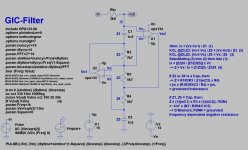
its a GIC lowpass filter synthesizing a frequency dependent negative resistance.
see an play with the asc")
jauu
Calvin
So that R144 is in parallel with the GIC-filter and R126/C130 make up a passive 6dB filter.
They tame the GIC´s peaking response with the post filtering.
C117 in U17A´s feedback loop is so small it just limits bandwidth and doesn´t belong to the post filter.
its a GIC lowpass filter synthesizing a frequency dependent negative resistance.
see an play with the asc
jauu
Calvin
You probabely missed out the Agnd node between R144/R118/C130The FDNR in your original schematic looks to be integrated into a MFB low pass in a config I've not come across before.
So that R144 is in parallel with the GIC-filter and R126/C130 make up a passive 6dB filter.
They tame the GIC´s peaking response with the post filtering.
C117 in U17A´s feedback loop is so small it just limits bandwidth and doesn´t belong to the post filter.
Attachments
Last edited:
- Status
- This old topic is closed. If you want to reopen this topic, contact a moderator using the "Report Post" button.
- Home
- Source & Line
- Digital Source
- Anyone work this out?????