The chip being the voltage amp stage usually gets fed with a similar supply voltage as the current amplifier consisting of output devices and optional drivers/pre-drivers.
You can feed the chip from the same supply rails as the output stage.
Or
You can feed a separate PSU with the same voltage as the output rails to the chip.
Or
You can feed a regulated and/or higher supply voltage to the chip.
The chip is safe to +-100Vdc (Vcc<=200V), but has much less protection than a chipamp.
I don't know what the chip does if the output demands more driving current than the chip specification.
I was just wondering about the voltage suggestions regarding this board +-45 and +-60vdc.
The chip has an operating voltage between 20v and 100v. I was hoping I could reuse this large toroidal I have around. It has a dual 60v line I would really like to use but +/-80VDC amp boards seem rare so I was hoping this one would actually need higher voltages.
I am just keen on NOT wasting anything... if there is a 30 + 60v line I would like to have a board which makes use of it.
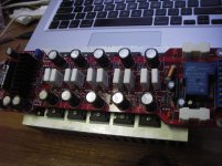
I have a couple of these boards and I tied the +/- 45 and +/- 60 volt lines together. ie +45 to +60 and -45 to -45. I use a +/- 65 volt power supply and get about 155-175 watts @8ohms depending on the power line voltage at the time of measurement. You will have to modify the Dc protect circuit a bit as it expects to see +45V, I took the almost finished amp to an Ottawa diy show and received very favorable comments concerning the sound quality. here is a link its post #123 13th picture, I think its labeled amp built by JK. The chasis is 17" x 10" x 2"
http://www.diyaudio.com/forums/clubs-events/176350-winter-diy-ottawa-meet-13.html
http://www.diyaudio.com/forums/clubs-events/176350-winter-diy-ottawa-meet-13.html
when you buy the boards a schematic is included. There is a series resistor between the DC protect IC and the relay. It is 560 ohms on my board. I replaced it with 2 4.7kohm 5 watt resistors in parallel. In series with one of the resistors is a led that tells me the relay is energized. The relay get about 16-18 volts which is plenty to energize it and keep it from getting too hot. If you use higher than 60-65 volts you may run into a problem with the maximum voltage rating of the IC protect chip uPc1237 and have to modify the board some more.
there is no advantage to use a supply for the driver chip that is way higher than the outputs. The +/- 45 pins are for the outputs and the +/- 60 pins are for the driver chip. Using 80 volts for the driver chip and 40 volts for the outputs is a waste and will severly limit your output power to around 70-80 watts instead of 250-300 with 80? volt rails.
Thankyou multisync. I just checked the schematic..
I was just hoping to use this large toroidal I have around. It is big, heavy and 1200va. I feel stupid not having found a suitable audio-oriented use for it.
Since it is 240v and secondaries are 30-0-30 + 60-0-60 I will probably have an unloaded line voltage of: 38-0-38vDC and 78-0-78v DC
What approach would you suggest in this case?
Will your output stage survive supply rails of +-80Vdc?1200va. ..................
Since it is 240v and secondaries are 30-0-30 + 60-0-60 I will probably have an unloaded line voltage of: 38-0-38vDC and 78-0-78v DC
What approach would you suggest in this case?
Connect the 30-0-30Vac as 60Vac.
Dual polarity rectify using single diodes for half wave rectification. Add some turns to increase this to say 65Vac if you want to regulate. Regulate each half down to a usable front end supply of +-80Vdc for Vcc=~160V <200V OK?
But before you do all that work try to identify the current rating of all four secondary windings.
BTW.
60Vac secondaries are likely to give >=+-90Vdc when on a light bias/quiescent current.
if you decide to buy the boards, you can take some time to look at the pcb traces for the uPC1237 chip and perhaps break a trace and isolate it from the pcb +45volt rail. You might then be able to use part of the 30-0-30 winding to provide the power for the DC protection and the 60-0-60 for the rest of the board, driver and outputs. I set the bias to an average of 30ma per output device. With my rails of +/- 65 volts or there abouts power dissipation at idle is 20 watts or so per channel. The heat sinks get a bit warm after a few hours.
All the power supply capacitors on the board are rated at 100 volts. So the board should survive +/-80. Use usual precautions when powering up for the first time. Remember there is no current limiting on the board for the output stages. one slip of a probe and poof
All the power supply capacitors on the board are rated at 100 volts. So the board should survive +/-80. Use usual precautions when powering up for the first time. Remember there is no current limiting on the board for the output stages. one slip of a probe and poof
R30 would seem the correct place to start to investigate reducing voltage to the chip. The absolute maximum would seem to be 60v...
Ah well I will probably end up using the 40v line for everything")
However I would really like to mess with this board...It looks like a robust design.
Ah well I will probably end up using the 40v line for everything
However I would really like to mess with this board...It looks like a robust design.
An externally hosted image should be here but it was not working when we last tested it.
Yep...
R30 + R26. If you have aymore suggestions looking at the schematic please tell me!
I could use a TL293 with some 2N3771 to builld a HV regulated powersupply and have a 60v line with a 38/40v
What I don't understand is why they chose 60v as the absolute maximum for the LME49810 chip. It can withstand up to +-100v. They should have stressed this voltage flexibility in the board's presentation yet all the vendors I contacted underline the 60v requirement as the high limit for this board.
AndrewT The schematic is not exactly correct, there are a number of small diferences. The board comes with 5 pairs of outputs not 3 as shown in the given schematic, the cap values are different, generally higher and a few other small? differences.
Some folks like to run the driver stage with a higher regulated supply or lower depending on your thinking. A driver stage with a higher voltage guarantees that it will not clip before the outputs, a higher output voltage stage than drivers, the clip flag will come on before the outputs clip. Six of one and a half dozen of the other. I just tied them together and be done.
It is difficult to design and impliment a board for $50 that works from +/-40 to +/-100 volts.
The add stretches the truth a bit.
I bought a couple of boards for fun, they were so cheap and surprise they work, very well, almost out of the box.
You get what you pay for.
- Status
- This old topic is closed. If you want to reopen this topic, contact a moderator using the "Report Post" button.
- Home
- Amplifiers
- Solid State
- Anyone recognise this Design..? based on LME49810