Hallo I need information on this ic: 3 terminals voltage regulator used in my telefunken S900 to bring the voltage to 15volt DC, on the component is write NEC D288 L76 nearly '78; wich circuit I can use to improve the turntable psu ? I would like to change the little transformer with a bigger one external to the chassis and I will be happy to use the same circuit with better components but, I don't know if it is a variable regulator and this mean that my new transf. (output 24V) shouldn't be good to replace the older one, but if the ic is a fixed regualtor it should work fine ??? Any idea? It is a 78 component (the little circuit in my telefunken report the following character on the downside of the PCB: Lenco 40481 -21/sep/1978
Bye,
Domenico
Bye,
Domenico
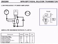
2SD288, and may have a zenner and a resistor around it
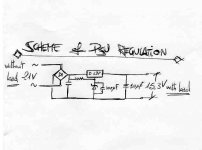
Also an output condenser to 15 volts...higher volt in the middle lead, the colector, and 15 volts to the base (the left lead)....the emitter may be 15.6 or 14.4, the rigth lead voltage, and those voltages will depends if the transistor is NPN or PNP.
As normal, Eva is rigth
regards,
Carlos
Also an output condenser to 15 volts...higher volt in the middle lead, the colector, and 15 volts to the base (the left lead)....the emitter may be 15.6 or 14.4, the rigth lead voltage, and those voltages will depends if the transistor is NPN or PNP.
As normal, Eva is rigth
regards,
Carlos
Dear brazillian friend, so You suggest me to replace the caps with ones rated with higher volt value? I haven't understand the part on the zener diode, that depends on the tipology of the IC (npn or PNP) it is referred only on the leg wich they are connected, it is only an explain assert, right?
Do
Do
The transistor...NPN the damned.
Here it is Kirochan..... when transistor is NPN, or PNP, the zener polarity changes and also the electrolitic filter polarity changes...all voltages polarities change.
Normally we use NPN to positive voltages, of course you can do the opposite.
And is more common to use PNP to negative voltages, of course you can do also in the opposite way.
Image is not so clear as we want...but the maximum voltage from colector to emitter is around 55 Volts, and maximum current 3 amperes....i suppose you can change your supply without fear...if the input voltage changed too much...and to higher side...example:
Original was 24 volts
New supply will be 45 volts
This way, increasing the voltage, you will have more voltage from colector to emitter.... as power is the product of this voltage by the current will cross this transistor, power will increase and heat too...as you know, you will need to replace, or include a heatsink, if you already did not made that.
The explanation is around basic Knowledge, because this is the knowledge I HAVE, and not knowing if you are a doctor or a beginner, it is adequated to explain in the most simplest possible way...if you are a doctor, sorry by this stupid basic informations.
Someone, starting, learning, will find use with my explanation.
regards,
Carlos
Attachments
If the DC voltage before the transistor is always above approx. 18V then there is no reason to replace the transformer other than aesthetics. On the other hand, using a transformer with higher output voltage will produce more heat in the regulator.
Replacing the discrete transistor-zener regulator by something like a LM317 IC may be sometimes useful if this 15V supply is powering small-signal circuits, though.
Also, placing the transformer outside the case in a separate box is only worth the effort when it was originally placed near sensitive small-signal circuits.
Thank you evrybody! It is the supply circuit for the motor of a direct drive turntable, so a stable and no disuturbed at all supply is a pretty solution.
Also good I think it will be create an external psu so the electromagnetic smog of the trasformer and 240V cable are far away from the cartridge. I'm going to modifing the psu in this way.
I want to replace the trasformer 'cause I got an unused a shielded 100vA 24 volt bigger and heavier than the little transformer in the Turntable chassis I think rated for 15VA, I'm not a doctor, I'm an electric engineering students, but the electronic course is in the next six month...so i have very little info on how a PSU regulation and transistor work.
Have a nice day It is usefull in your opinion bypass the 10Uf and the cap on the zener with a poliester MKP 0,1 Mf cap to filter higer frequency?
- Status
- This old topic is closed. If you want to reopen this topic, contact a moderator using the "Report Post" button.
- Home
- Amplifiers
- Solid State
- anybody knows this ic????