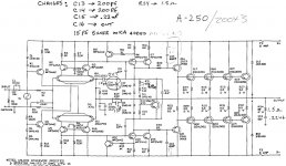
It is a 3 channels power amp. There is no model number other than 200X3!!! I just want to see whether there is any way to improve the sound quality. I don't have the schematic, I got it 16 years ago.
1) I don't use the third channel, should I disconnect the third channel from the PS?
2) Will increasing the PS filter cap improve the sound? Something from simple to more complicate.
3) I remember it has really big electrolytic caps, will paralleling caps of lower value and even film caps to lower the ESR help?
4) Paerallel wires to beef up the output connections, beef up the high current traces.
Where can I get the schematic of Acurus?
Thanks
I have no problem with the amp, I just want a better amp!!! I have been on the tube side for a few days and is getting very confused. Don't think I can make up my mind what to build yet. So at the mean time, next best thing is to find some not too invasive way to improve the sound of the amp slightly. I don't have any experience in audiophile amps at all. I always want a better amp, so instead of keep building guitar amps, why not try building an audiophile amp for my next project that I can actually enjoy 6 hours a day.
Ha ha, you are all over different forums!!!
Thanks
Ha ha, you are all over different forums!!!
Thanks
Last edited:
Where can I get the schematic of Acurus?
Why don't you try contacting them through their website? Took me less than two minutes to find it.

www.acurusav.com - amplifiers
jeff
Break the supply lines to the front end and insert a small value resistor for isolation. Now add bypass caps on the front end (suggest 100µF plus 0.1µF film), add bypass caps to output stage, try around 47µF plus 0.1µF film with a 1Ω resistor in series.
See Leach amplifier schematic.
http://electronics-diy.com/schematics/991/leachamp_schema.png
See Leach amplifier schematic.
http://electronics-diy.com/schematics/991/leachamp_schema.png
Break the supply lines to the front end and insert a small value resistor for isolation. Now add bypass caps on the front end (suggest 100µF plus 0.1µF film), add bypass caps to output stage, try around 47µF plus 0.1µF film with a 1Ω resistor in series.
See Leach amplifier schematic.
http://electronics-diy.com/schematics/991/leachamp_schema.png
Thanks
You mean adding R32, R33, C13, C14, C15 and C16 to isolate and bypass the differential and the current mirror stages.
Then add smaller caps like 47uF and 0.1uF ceramic caps in parallel with the huge caps onto the pcb to lower the ESR and better high frequency bypass.
"You mean adding R32, R33, C13, C14, C15 and C16 to isolate and bypass the differential and the current mirror stages."
Exactly.
"Then add smaller caps like 47uF and 0.1uF ceramic caps in parallel with the huge caps onto the pcb to lower the ESR and better high frequency bypass. "
C21, 22, are 22µF in the Leach, C23, and 24 are 0.1µF, but add a 1Ω in case you have grounding issues (causing oscillations).
You may also want to add C2, 3, 4, 5 (Leach) to D3, 6 (Accurus).
Try increasing C12 to 2.2µF (or even higher), this will change the way the bass will sound.
I would try removing Q1 and Q8 and run resistors as the CS as per the Leach.
You could also try splitting the driver emitter resistor and using it as a feedback point (as per the Leach), may require an oscilloscope and a lot of fiddling.
Unfortunately you can't degenerate the diff pair like a Leach (because of the dual transistor package, although you could use matched discretes glued together).
Thanks a million. I pull one of the power amp out already and still make the other two work in the system. So I can take my time fiddling with the one amp outside. So far, I check all the transistors numbers and both the Q number and the part numbers match the schematic. I check a few components and they match too. So I think the schematic I posted is the right one.
I have to remove the pcb from the heat sink to do anything as the traces are all under the board. I definitely going to double up the output wires as the wires are like 16 gauge only. The jumpers are also very thin.
I will look into your suggestion after I open it up.
Thanks
I have to remove the pcb from the heat sink to do anything as the traces are all under the board. I definitely going to double up the output wires as the wires are like 16 gauge only. The jumpers are also very thin.
I will look into your suggestion after I open it up.
Thanks
C21, 22, are 22µF in the Leach, C23, and 24 are 0.1µF, but add a 1Ω in case you have grounding issues (causing oscillations).
You may also want to add C2, 3, 4, 5 (Leach) to D3, 6 (Accurus).
Try increasing C12 to 2.2µF (or even higher), this will change the way the bass will sound.
Hi DJK
I ring out the circuit, it's matches the schematic I posted. I feel a lot better. It is easy to do part of the mod you suggested. On top this is what I am going to do:
1) I am going to put 10uF caps across D1 & D2 string, and D4 & D5 chain and beef up the ground trace from D1 to R5, D5 and R12. Then to the input ground.
2) Beef up the ground trace between the ground of C6 and C7 to the input. This is to reference the NFB ground to the input.
3) I am going to increase the resistors you suggested to isolate the +/-V to the input and driver side from 1 ohm to 51 ohm. This is between R10 and collector of Q16, and R17 and Q21. I calculate the current drawn of the input and pre-driver from each rail, it's only 12mA. Let's just say 25mA. 51 ohm only drop 1.25V on each side. Q16 and Q21 are both emitter follower, their is no problem if their +/-V rail is different by 1.25V. then the filter caps will work a lot better.
4) Should I increase the idle current by adjusting R11 to get more current through the power transistors to get more into the Class A region.
I think it's better to leave Q1 and Q8 there as these are constant current sources or CCS. CCS improve power supply rejection.
What else can you think of?
I have a question, these circuits are so standard. What make an amp that has a $5000 sound vs $1000 amp like this one?
Thanks
Last edited:
...
I have a question, these circuits are so standard. What make an amp that has a $5000 sound vs $1000 amp like this one?
Thanks
Oh, that's a loaded question...
In some cases, i suspect that the price tag and the blingy machined chassis / enclosure are the only things that make that multikilobuck sound.
In other cases I suspect it is a designer who pays attention and makes improvements like what you are trying to make here, especially if he doesn't have to pinch every penny in the BOM and the assembly practices, but that's still fairly standard I guess, just fewer compromises.
Finally there are a few really innovative and/or balls-to-the-wall designs like Pass labs or Halcro that aren't so standard.
But in any of those conscientious or innovative or extreme amps, is it _really_ the amplifier sounding different or is it that price and lovely chassis again?
Someone should try putting those designs in plain chassis and selling them for thin margins. I suspect they then won't sound as good and therefore won't sell in high enough volumes to make feasible the thinner margin.
I have a pair of old PS Audio amps that I fried years ago by clumsily slipping test probes and shorting something while trying to measure something about their operation-- I think I was planning to put in a dc servo loop.
and I am torn about whether to go back and repair and try to improve them, or just adapt a new design to some pcbs that I would design to fit exactly on the existing heat sinks.
In any case, and forgive me for what may be obvious or unnecessary advice, I would like to suggest you to not ever try to use handheld multimeter probes while trying to adjust bias, offset, measure test points, etc. It is way to easy to short something out and blow up your amp. So easy I did it twice. When I fried the first one I thought ok I obviously will be careful enough with the second one. Yet I fried it as well. So get clip leads, minigrabbers, so that you aren't probing around with the amp on.
"I think it's better to leave Q1 and Q8 there as these are constant current sources or CCS. CCS improve power supply rejection."
What could be more constant than a resistor to a zener stabilized voltage (Leach)?
Active CCS usually measure a bit better, but passive CCS frequently sound better.
The only real reason I can see to keep Q1 and Q8 is the over-temp thermostat shuts off the CCS when the amp overheats.
You're welcome to play with the bias, but tests with an IM analyzer show this type of circuit has a sweet spot for the bias that is actually quite low, and cranking it up will increase IM distortion at higher frequencies.
These are just suggestions, YMMV.
The v4.5 Leach was the result of over 20 years of refinement, it's hard to improve without starting with a blank sheet of paper and a whole different approach.
There are, or at least used to be, a lot of small audio manufacturers seeking to profit from those with the cash who consciously support local manufacturers, believing they can deliver better quality products which justify higher than import prices.
I think that's been a dubious situation everywhere assembly costs are high and ever since silicon became the the semiconductor of choice. Many are stuck with such audio products that are lemons from the past and look for ways to turn them into high-end products but don't have the skills or knowledge to tweak designs to the perfection they want - if such is actually possible with their product.
You can follow the standard recipes you find here and all over the 'net for souping-up amplifiers which basically involve recapping, super-sizing flimsy ones, filtering noise better with more and better parts. Basically, you are throwing money at it in a shotgun approach to improving or at the least restoring original performance but this doesn't, IMV, give you $5,000 or rather $20,000 sound. It just makes the sound with all it's original faults, that much clearer above noise. Some are happy with that benefit alone. Others want to hear rich harmonics that enhance spatial and tonal effects as do many high-end products - ostensibly those using tubes to gain that "extra" that is often avoided in the explanation as to why they are still used.
That loaded question again and adding mine, asking what your idea of $5,000 sound is.
In my area, $5,000 US can buy you a big, reasonable sounding amp or a quite good sounding small-medium. amp, They may be premium models from budget brands or vice-versa. Either way, there is always some unaffordable masterpiece that will sound better from an imagined perspective, at least.
The reason I am searching for better sound was because I bought the Acurus when I had a pair of Kef floor speaker. Then I bought a pair of JM Lab that is much higher quality. In the process of testing the JM Lab, I actually brought my Acurus to the store and ran the speaker. My big mistake was I compare the Acurus with a Ybl amp there. It was day and night difference. The Ybl sound fuller and richer with my speaker. Everything else was the same, same song, same preamp, same speaker and same room. Just A/B comparison.In my area, $5,000 US can buy you a big, reasonable sounding amp or a quite good sounding small-medium. amp, They may be premium models from budget brands or vice-versa. Either way, there is always some unaffordable masterpiece that will sound better from an imagined perspective, at least.
I take up amp building as a hobby, built two guitar amps, I think it's time to build an audiophile amp. I was in the tube section here, but I still have lot to learn about audiophile electronics. So I decided to work on my Acurus as a stop gap for now and wait until I learn more and decide on what to build.
I am sure there are easy things I can improve a little. I remember I went into the Kef and beefed up the wiring and the traces in the crossover, it did improve the sound a little. I think even the manufacturer sometimes over looked the interconnect and pay too much attention on the circuit and electronics. Simple beefing up the connections sometimes can do magic.
I traced the input ground traces, it uses thin 12mil trace running all over. I beefed up with 16 gauge wire, adding filter caps on the zener and separate the front end from the power section. We'll see whether that improves a little.
One main reason I am reluctant to remove Q1 and Q8 is I would be doing big changes. And I need good reason for that. Are you saying using resistor tail make the sound better?"I think it's better to leave Q1 and Q8 there as these are constant current sources or CCS. CCS improve power supply rejection."
Active CCS usually measure a bit better, but passive CCS frequently sound better.
The only real reason I can see to keep Q1 and Q8 is the over-temp thermostat shuts off the CCS when the amp overheats.
The v4.5 Leach was the result of over 20 years of refinement, it's hard to improve without starting with a blank sheet of paper and a whole different approach.
I can think of one reason constant current is better. The amp is like an opamp in non inverting configuration. This means the input of the differential pair move up and down with the input signal. This in turn change the tail current and give modulation. Constant current source is superior in the common mode rejection column, that's the reason all IC opamp use constant current source for the tail.
I am not familiar with Leach. Is it supposed to be high end amp? Other than the Q1 and Q8, the design between the Leach and my Acurus are quite similar.
A resistor to a constant voltage with a constant load is by definition CONSTANT CURRENT.
As I said that the power amp is very similar to an opamp in non inverted configuration. The differential pair bounce up and down with the input voltage. The input can move +/-1V. The tail resistor will follow the input and the tail current change with the input swing. That's why you need constant current source. BUT that does not mean it sounds better with constant current. Maybe the modulation of current improves the sound.
Do you know what is the zener voltage Leach use to set the voltage across the tail resistor?
Here, look at the Eagle drawn schematic and B.O.M. for the 4.5 version.
The Leach amp 200W amplifier
The Leach amp 200W amplifier
Member
Joined 2009
Paid Member
It is way to easy to short something out and blow up your amp.
Yup, done that too !
- Status
- Not open for further replies.
- Home
- Amplifiers
- Solid State
- Any way to improve the sound of my Acurus.