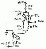
In AB2? With a mere 12AU7 to flog the grids?
"flog the grids" - I like it!
As discussed, only 7 mA rms current is needed to drive AB2 807 PP stage to 120 W. 12AU7 cathode follower idling at 10 mA can deliver it. Taking into account that originally posted GE amplifier puts out much less ambitions 30 W, it probably stays in AB1 all the time.
An AB2 follower doesn't necessarily need a high idle current - remember you're sourcing a high current into the grid in a highly non-linear fashion, so as long as the driver is otherwise linear with its operating point for AB1 operation, it should work fine into AB2. Although, one argument for running at a high current is to already be running the follower at higher Gm before grid current is needed, but to be honest the distortion profile, even if kept low by feedback, is probably pretty ugly by that point (but still better than limiting) so possibly not too big a difference or big deal.
Last edited:
6bl7's and 6bx7 work very well as cathode followers to drive out put tubes.
There are lots of excellent speakers that do not need high damping factor amplifiers such as Altec 515 and many JBL's; i use small amounts of feedback about 12DB. with many modern speakers are designed for transistor amplifiers or the boom is excessive; hard to understand why use them for tube amplifiers anyway.
Phil
This dog is very sick.
It is almost a quiz: how many things can you find wrong?
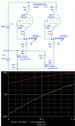
As drawn, the bias is NOT the -18V noted on the plan, but adjustable from PLUS 24V to Plus 49V.
I got that by finger-sketching but asked the SPICE to refine the numbers. For simplicity I modeled one side, doubling the common resistances to work the same.
The "obvious typo" would be R23 R24 swapped, so I did that also. Bias adjusts Negative 45V to Plus 24V. Yes, -18V is in there, but so are a LOT of 6L6-burning points. Over half the pot range is dangerous to the 6L6es. Yes you need some slack for 6L6 variations, but you never want half the pot range +positive+.
I will accept a "7mA peak grid current" number. The 12AU7 run 6mA idle current, so 7mA is not "small". The 6L6 grids are taken below C8 C9, and grid current will charge these caps, causing bias-shift when it gets to AB2. Further, the grid current adds to R21 current, so the voltage at C11 will drop. Slowly, because C11 is quite large, but faster than you can read an output meter.
Is this really from G.E.? It has the feeling of an article from a magazine.
Attachments
while olden 6L6G tubes have g1's that can take grid currents in AB2,
i wonder if new production tubes can do the same....
any study about this? anyone?
btw, my recent quads of JJ6L6GC's biases exactly the same to my amazement...
up to the first decimal point....!!!
sound is very good too...
i wonder if new production tubes can do the same....
any study about this? anyone?
btw, my recent quads of JJ6L6GC's biases exactly the same to my amazement...
up to the first decimal point....!!!
sound is very good too...
This dog is very sick. <snip>
You are correct pointing at these lapses. In addition to negative rail adjustment screw-up, 6L6 control grids should be connected directly to 12AU7 cathodes, value of R21 is wrong, and drawing ~20 mA from half-way rectifier will in all likelihood kill the power transformer. But, as has been said, for 30 W output power, the stage will stay in AB1, maybe with just a whiff of AB2, so CF current capability is not a problem.
The Allen schematic that I posted is free of these inconsistencies. That circuit's CF idle current is only 0.6 mA.
- Status
- This old topic is closed. If you want to reopen this topic, contact a moderator using the "Report Post" button.

